
Geophysical Signal Denoising Method

A geophysical and signal technology, applied in the field of engineering geophysical exploration, to achieve good signal denoising effect and accurate detection results

Active Publication Date: 2019-09-10
WUHAN ENG SCI & TECH RESINST
View PDF2 Cites 0 Cited by
  • Summary
  • Abstract
  • Description
  • Claims
  • Application Information

AI Technical Summary

Problems solved by technology

However, the existing various denoising methods cannot well meet the needs of engineering applications.

Method used


Image

  • Geophysical Signal Denoising Method
  • Geophysical Signal Denoising Method
  • Geophysical Signal Denoising Method

Examples


Embodiment Construction

[0020] Below in conjunction with accompanying drawing and specific embodiment the present invention is described in further detail:

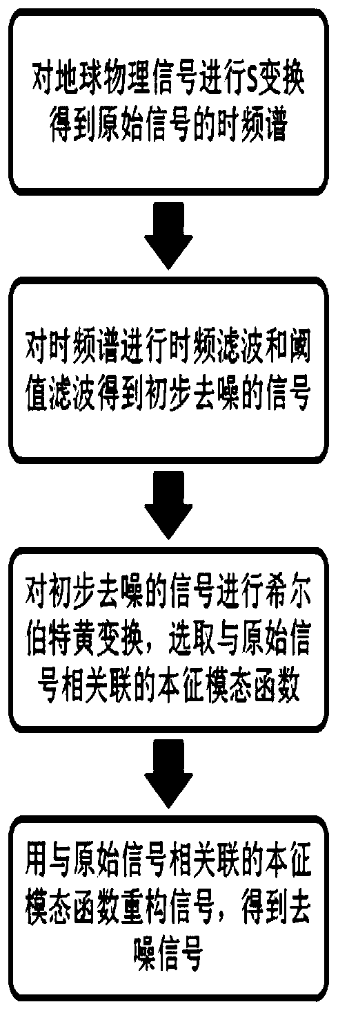
[0021] Such as figure 1 The shown geophysical signal denoising method comprises the following steps:

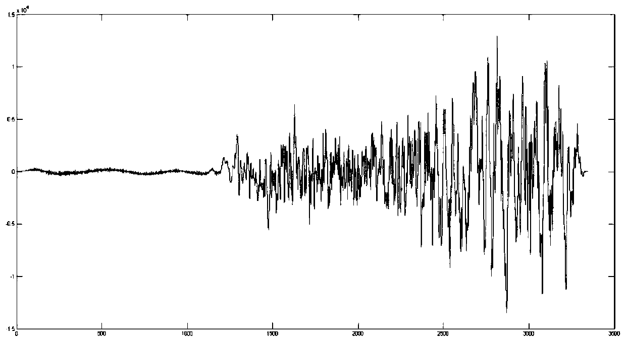
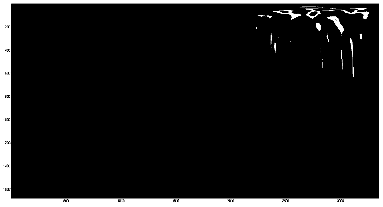
[0022] Step 1: For the original geophysical signal (seismic signal, bolt detection signal, foundation pile detection signal or radar signal, here we take the seismic signal as an example, such as figure 2 As shown, the abscissa is time, and the ordinate is the displacement of the sensor) to carry out stockwell transformation to obtain the time-frequency spectrum of the original geophysical signal (such as image 3 As shown, a certain seismic acquisition signal S transform spectrum, its abscissa represents time, ordinate represents frequency, brightness represents the energy size of this point);

[0023] Step 2: performing time-frequency filtering on the time-frequency spectrum of the original geophysical signal obtained in step 1;

[0024] ...


PUM


Abstract

The invention discloses a method for denoising a geophysical signal. The method herein includes the following steps: 1. conducting S transformation on an original geophysical signal, obtaining the time-frequency spectrum of the original geophysical signal; 2. conducting time frequency filtering on the time-frequency spectrum; 3. conducting threshold filtering on the signal after the time frequencyfiltering; 4. conducting s inverse transformation on the result from the threshold filtering, obtaining an initial denoised signal; 5. conducting empirical mode decomposition on the initial denoisedsignal, obtaining a plurality of intrinsic mode function components of the initial denoised signal; 6. conducting hilbert transformation and spectrum analysis on all the intrinsic mode function components of the initial denoised signal, selecting an intrinsic mode function which is associated with the original geophysical signal; and 7. reconstructing a signal by using the intrinsic mode function,obtaining the required denoised signal. According to the invention, the method herein can efficiently denoise the geophysical signal.

Description

technical field [0001] The invention relates to the technical field of engineering geophysical exploration, in particular to a method for denoising geophysical signals. Background technique [0002] Engineering geophysical prospecting, referred to as engineering geophysical prospecting, its detection target is the underground rock and soil layer or building structure. After loading the natural or artificial physical field on the detection target, observe its changes through instruments to determine the spatial range (size, shape, etc.) of the concealed target. , distribution), and measure the physical parameters of the target body to achieve a physical exploration method to solve geological problems. At present, the technical means of engineering geophysical prospecting mainly include elastic wave method and electromagnetic wave method. [0003] Since the targets to be explored in engineering geophysical prospecting are usually shallower in depth and have smaller defects, n...

Claims


Application Information

Patent Timeline
Patent Type & Authority Patents(China)
IPC IPC(8): G01V9/00G01V1/36
Inventor 金彦周超叶辉刘玉郭俊峰
Owner WUHAN ENG SCI & TECH RESINST
Learn More