
Paper processing apparatus

A paper processing, racking technology, used in devices that accept coins, process coins or valuable banknotes, instruments, etc.

Pending Publication Date: 2018-01-26
KUNSHAN GUAO ELECTRONICS MACHINERY
View PDF4 Cites 0 Cited by
  • Summary
  • Abstract
  • Description
  • Claims
  • Application Information

AI Technical Summary

Problems solved by technology

[0002] Existing ATM machines usually have a processing mechanism for feeding in or sending out banknotes for the operation of depositing or withdrawing by the user. In this process, since the banknotes are stacked irregularly in both the direction and length of the banknotes, and the oil stains on the banknotes during use cause several banknotes to be glued together, it is difficult to neatly place the banknotes individually. input or output

Method used


Image

  • Paper processing apparatus
  • Paper processing apparatus
  • Paper processing apparatus

Examples


Embodiment approach

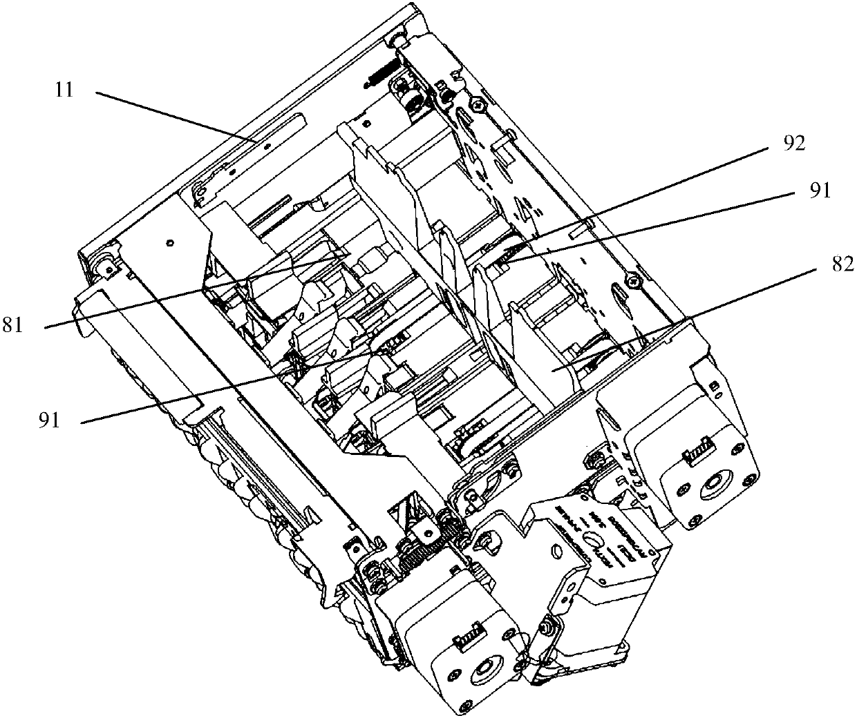
[0030] In further embodiments of the present invention, please continue to refer to Figure 1 to Figure 3 As shown, the front side and the rear side of the banknote holder plate 81 are respectively provided with a drive wheel 91, and a conveyor belt 92 is surrounded on the two drive wheels 91. The lower end of 82 is fixedly connected. The forward rotation and reverse rotation of the two drive wheels 91 drive the conveyor belt 92 to move back and forth, thereby driving the push plate 82 to move back and forth, thereby realizing the effect of pushing banknotes.

[0031] In a further embodiment of the present invention, both transmission wheels 91 are gears, and the conveyor belt 92 is a gear belt.

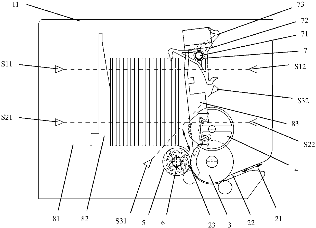
[0032] In a further embodiment of the present invention, the second impeller 7 and the separating wheel 3 are respectively located on the left and right sides of the guide plate 83 .

[0033] In a further embodiment of the present invention, a banknote inlet 23 is formed between th...


PUM


Abstract

The invention discloses a paper transmitting mechanism. The mechanism includes a machine frame which is disposed in the middle of an ATM machine. The machine frame is provided with a bill insertion slot thereabove and is provided with a bill channel therebelow. The front side of the machine frame is provided with a bill port which is in communication with the bill channel. A separating wheel is disposed above the bill channel. A bill twisting wheel is disposed above the separating wheel. A bill blockage wheel is disposed behind the separating wheel. A first blade and the bill blockage wheel are co-axially disposed. The bill blockage wheel is provided with a bill holding plate thereabove. The upper end of the bill blockage wheel protrudes from the bill holding plate. The bill holding plateis vertically provided with a pushing plate thereon for movably pushing bills. The bill holding plate is provided with a guide plate on the rear side approaching the separating wheel. The upper side of the guide plate is provided with a second blade. According to the invention, the first blade is disposed on the shaft of the bill blockage wheel and is cooperated with the second blade, the bill twisting wheel and the separating wheel, so that the paper transmitting mechanism can input or output papers that are piled in a mess one by one.

Description

technical field [0001] The invention relates to the technical field of paper processing, in particular to a paper processing device. Background technique [0002] Existing ATM machines usually have a corresponding processing mechanism for feeding or sending banknotes in or out for users to deposit or withdraw. Among them, since the banknotes are stacked irregularly in both the direction and length of the banknotes, and the banknotes are glued together due to oil stains and other reasons during use, it is difficult to neatly arrange the banknotes individually. input or output. Contents of the invention [0003] In view of the above-mentioned problems, the object of the present invention is to provide a sheet processing device. [0004] In order to achieve the above object, the technical scheme that the present invention takes is: [0005] A paper processing device, including: a frame, the frame is arranged in the middle of the ATM machine, the top of the frame is provide...

Claims


Application Information

Patent Timeline
Patent Type & Authority Applications(China)
IPC IPC(8): G07D11/00
Inventor 陈崇军徐新华彭晓东
Owner KUNSHAN GUAO ELECTRONICS MACHINERY
Features
  • Generate Ideas
  • Intellectual Property
  • Life Sciences
  • Materials
  • Tech Scout
  • Unparalleled Data Quality
  • Higher Quality Content
  • 60% Fewer Hallucinations
Learn More