Sanitary line attachment

A connection and pipeline technology, applied in the direction of pipe/pipe joint/pipe fitting, sealing surface connection, passing through components, etc., can solve problems such as non-installation, error, user neglect, etc.

Active Publication Date: 2018-01-26
NEOPERL
View PDF6 Cites 0 Cited by
  • Summary
  • Abstract
  • Description
  • Claims
  • Application Information

AI Technical Summary

Problems solved by technology

However, there is a danger here that the user neglects o

Method used


Image

  • Sanitary line attachment
  • Sanitary line attachment
  • Sanitary line attachment

Examples


Embodiment Construction

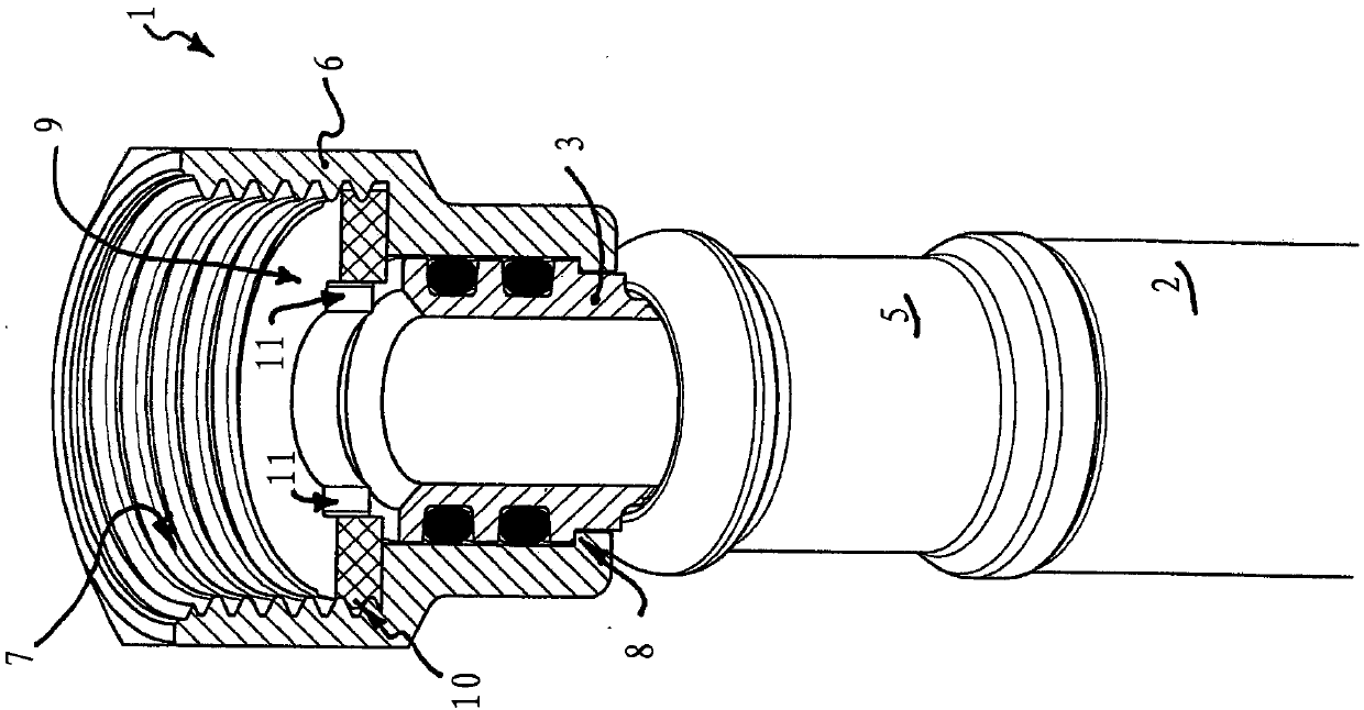
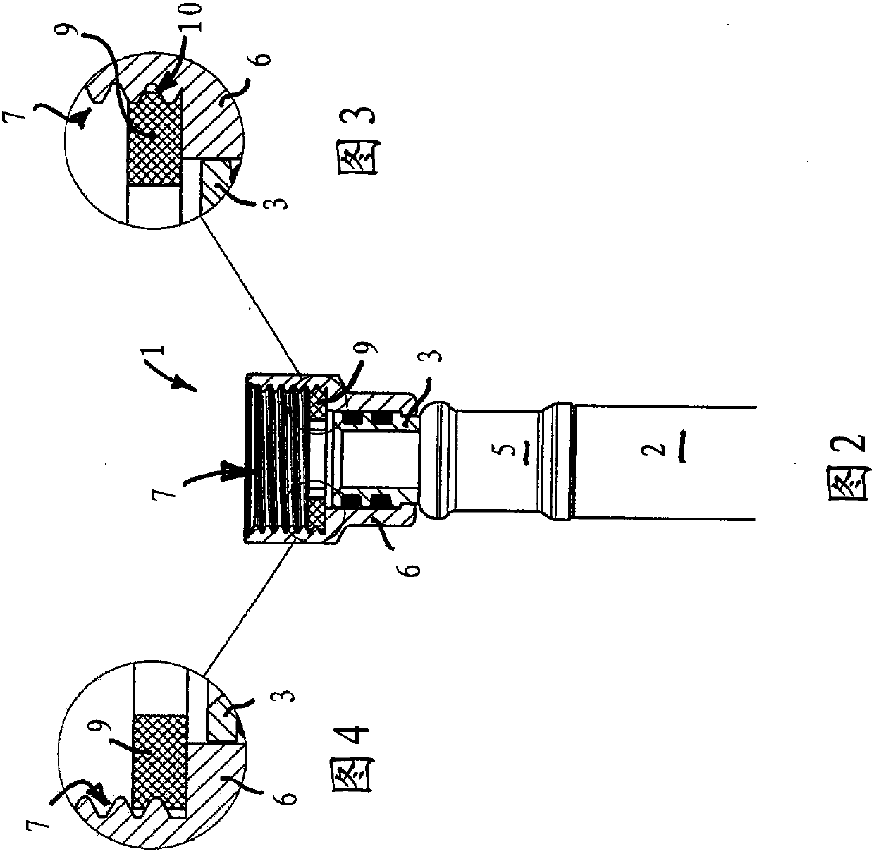
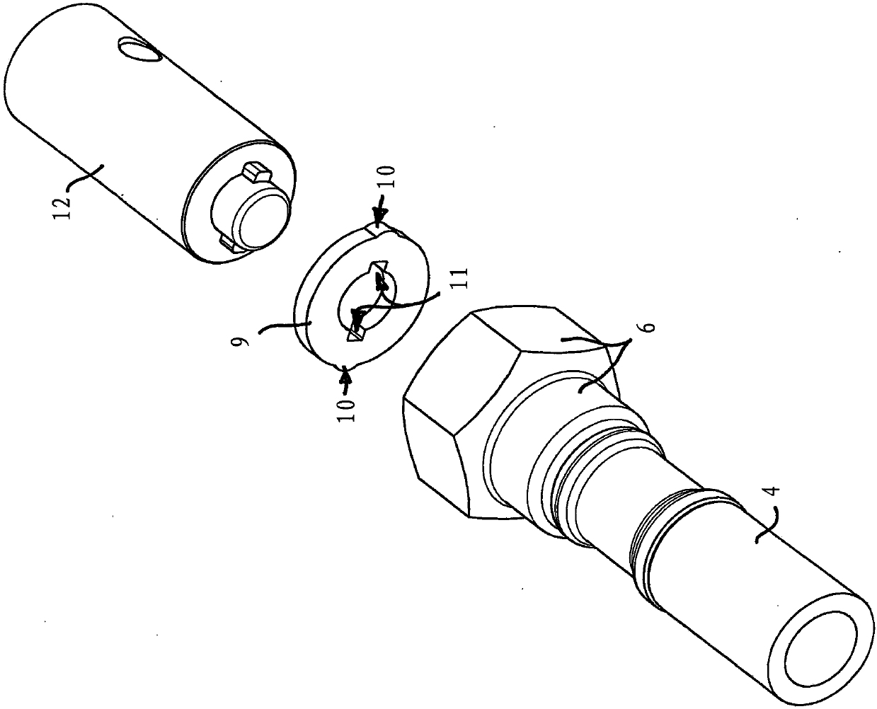
[0022] Figure 1 to Figure 3 A sanitary line connection 1 is shown, which is designed here as a hose connection for a flexible water hose 2 . The line connection 1 comprises a pipe connection 3 with a nipple 4 onto which one of the hose ends of the flexible hose is slipped. The hose end is held on the nipple 4 by a crimped crimp sleeve 5 which surrounds the hose end of the water hose 2 .

[0023] The line connector 1 shown here comprises a sleeve-shaped end region 6 which is provided in its sleeve interior for connection to an adjacent line section (not shown further here). The internal thread 7. The sleeve-shaped end region 6 is here formed by a union nut. On its end region facing away from the internal thread 7, the union nut engages from behind an annular shoulder 8 arranged on the pipe connection 3 in such a way that the union nut is held on the pipe in an axially immovable manner, although rotatable. Connector 3.

[0024] In order to seal the interface between the li...


PUM


Abstract

The invention relates to a sanitary line attachment (1) which has a sleeve-shaped design in at least one front end area (6) and, in the sleeve interior of this sleeve-shaped front end area (6), has aninner thread (7) for attachment to an adjacent line section, wherein at least one sealing ring (9) is clamped sealingly between the line attachment and the adjacent line section, from the outer circumference of which ring at least one holding projection (10) protrudes, which holding projection (10) engages in the inner thread (7) in the sleeve interior of the sleeve-shaped front end area (6). A characteristic of the line attachment (1) according to the invention is that the sealing ring (9) is made from a dimensionally stable and/or inelastic material, and that the sealing ring (9) has at least one indent (11), preferably at least two indents (11) arranged at a distance from each other on the inner circumference of the ring, which indents (11) are designed as tool engagement surfaces (cf.Fig. 5).

Description

technical field [0001] The invention relates to a sanitary line connection which is sleeve-shaped in at least one end region and which is provided in the sleeve interior of the sleeve-shaped end region for connection to an adjacent line section. wherein a sealing ring is provided for sealingly clamping between the pipeline connection and the adjacent pipeline section, the sealing ring has at least one protruding retaining protrusion on its ring periphery , the retaining projection engages in an internal thread in the sleeve interior of the sleeve-shaped end region. Background technique [0002] A sanitary line connection of the type mentioned at the outset is known from EP1770225B1. In at least one end region of this known line connection part, a sleeve-like design is provided, in the sleeve interior of which end region an inner cavity for connection to the inflow-side or outflow-side line section is provided. thread. In the end region, a sealing ring is tightly clamped b...

Claims


Application Information

Patent Timeline
IPC IPC(8): F16L19/02
Inventor W·库里
Owner NEOPERL
Why Eureka
Try Eureka