
Image processing device, image processing method and 3D image generation system

a technology of image processing and image generation, applied in optics, instruments, electrical appliances, etc., can solve the problems of people feeling dizzy and nauseous, image generation units of multi-focus display systems may have abnormal display content, and have a great negative impact on user experien

Active Publication Date: 2022-10-06
CORETRONIC
View PDF18 Cites 0 Cited by
  • Summary
  • Abstract
  • Description
  • Claims
  • Application Information

AI Technical Summary

Benefits of technology

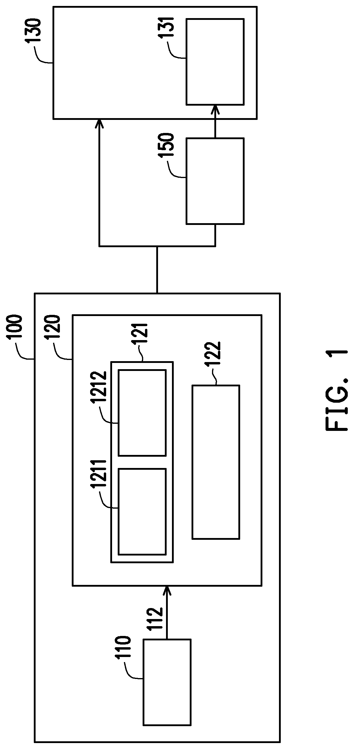
The patent describes an image processing device and method that ensures the correctness of transmitted data content and takes into account the smoothness of the display image in a limited bandwidth. The device merges image data containing multiple depth plane images and zoom control information and transmits it through a processing circuit. This ensures that the image is not incorrect due to processing speed and transmission rate factors. The device also accurately determines the time at which each depth plane image and zoom control information is transmitted to the display device and zoom lens, ensuring the smoothness of the image. Overall, the patent provides a solution for transmitting and processing image data in a reliable and efficient manner.

Problems solved by technology

This phenomenon violates physiology of vision and leads to vergence-accommodation conflict, which causes people to feel dizzy and nauseous.
In detail, an image generation unit of the multi-focus display system may have abnormal display content due to the following reasons, such as unable to complete sub-image processing of the 3D scene being in time (for example, due to the processing speed not being fast enough), an insufficient transmission rate, and the image generation unit transmitting the data content at an incorrect time.
The above-mentioned problems have a great negative impact on the user experience.

Method used


Image

  • Image processing device, image processing method and 3D image generation system
  • Image processing device, image processing method and 3D image generation system
  • Image processing device, image processing method and 3D image generation system

Examples


Embodiment Construction

[0044]In the following detailed description of the preferred embodiments, reference is made to the accompanying drawings which form a part hereof, and in which are shown by way of illustration specific embodiments in which the invention may be practiced. In this regard, directional terminology, such as “top”, “bottom”, “front”, “back” etc., is used with reference to the orientation of the figure(s) being described. The components of the present invention can be positioned in a number of different orientations. As such, the directional terminology is used for purposes of illustration and is in no way limiting. On the other hand, the drawings are only schematic and the size of the components may be exaggerated for clarity. It is to be understood that other embodiments may be utilized and structural changes may be made without departing from the scope of the present invention. Also, it is to be understood that the phraseology and terminology used herein are for the purpose of descripti...


PUM


Abstract

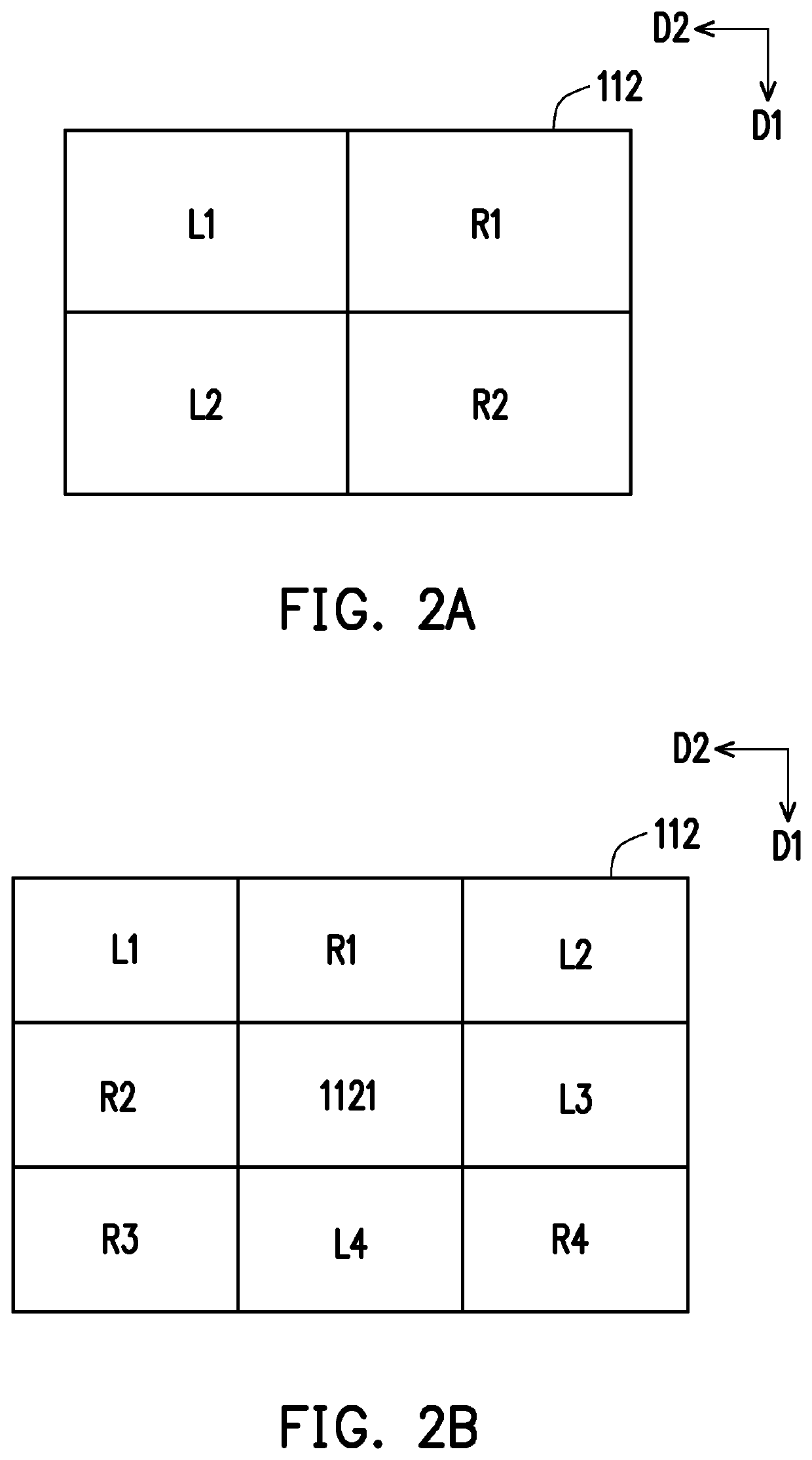
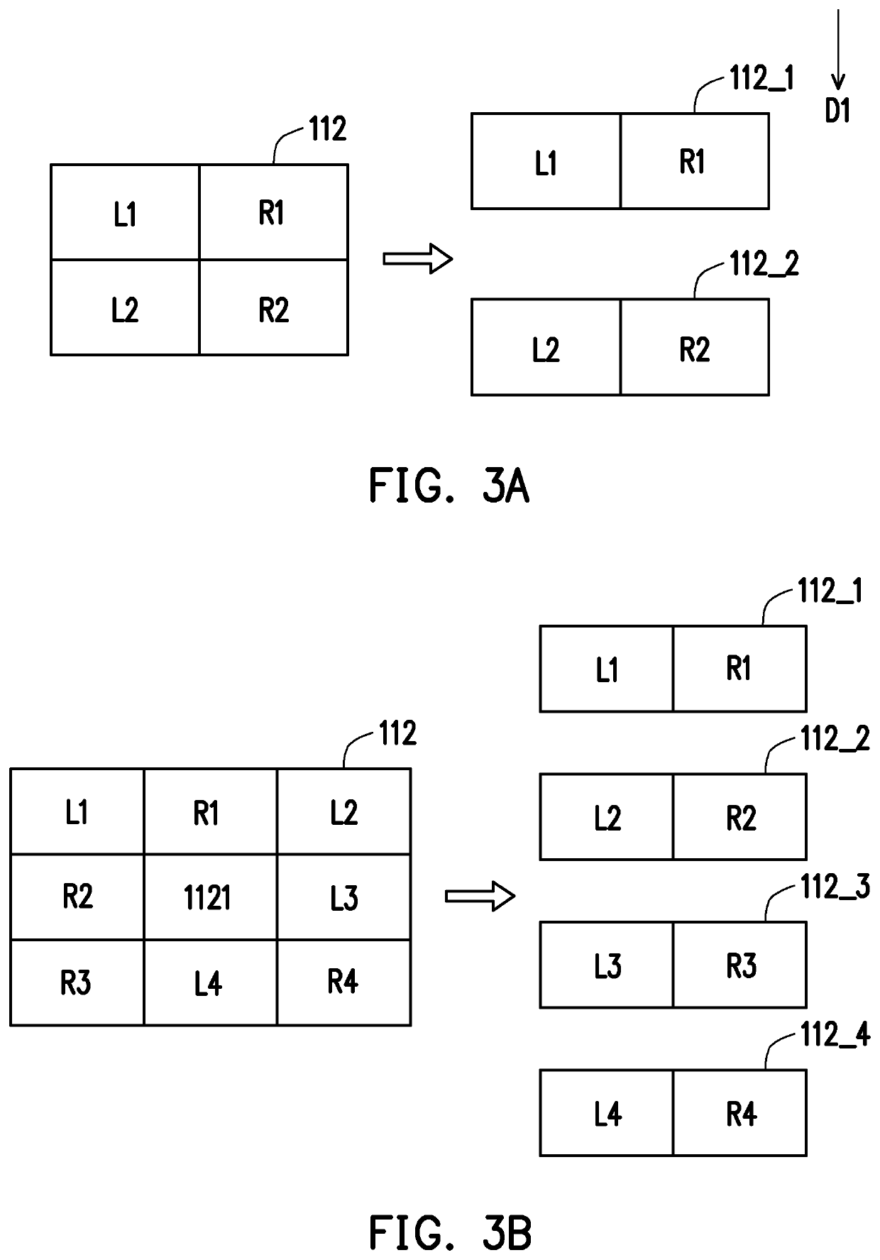
An image processing device, including an image generation circuit and a multifocal length processing circuit, is provided. The image generation circuit generates multiple depth plane images with depth information and multiple corresponding zoom control information, and merges the multiple depth plane images and the multiple zoom control information according to an arrangement rule, to be a merged image data. The multifocal length processing circuit is configured to decompose the merged image data to restore the multiple depth plane images and the corresponding multiple zoom control information according to the arrangement rule, and to determine a time at which the restored multiple depth plane images are transmitted to a display device and a time at which the restored multiple zoom control information are transmitted to a zoom lens according to a frame rate of the display device. The disclosure also provides an image processing method and a 3D image generation system.

Description

CROSS-REFERENCE TO RELATED APPLICATION[0001]This application claims the priority benefit of Taiwan application serial no. 110111820, filed on Mar. 31, 2021. The entirety of the above-mentioned patent application is hereby incorporated by reference herein and made a part of this specification.BACKGROUNDTechnical Field[0002]This disclosure relates to relates to an image processing device, and in particular to an image processing device that processes 3D images.Description of Related Art[0003]Currently, in the 3D image generation technology, the human eye may focus on any virtual object in a virtual environment after an image generated by a virtual environment system comes into the retina. However, each virtual object does not emit light with a degree of divergence corresponding to its location. This phenomenon violates physiology of vision and leads to vergence-accommodation conflict, which causes people to feel dizzy and nauseous.[0004]In response to this issue, a display panel capab...

Claims


Application Information

Patent Timeline
IPC IPC(8): H04N13/395H04N13/398H04N13/194H04N13/156H04N13/178H04N13/161
CPCH04N13/395H04N13/398H04N13/194H04N13/156H04N13/178H04N13/161G02B15/14H04N13/322H04N2013/0081H04N23/67H04N23/951H04N23/667H04N23/69
Inventor CHANG, HSIN-YUEHCHEN, LI-MING
Owner CORETRONIC
Learn More