
Shift frequency demultiplier with automatic reset function

a technology of automatic reset and demultiplier, which is applied in the direction of oscillation generator, continuous circulation pulse counter, and counting chain synchronous pulse counter. it can solve the problems of shifting frequency demultiplier with more complex control logic, inability to normally recover, and inability to produce entire errors directly. it achieves simple structure, ensures the correctness of the frequency demultiplication, and is easy to use.

Active Publication Date: 2011-12-08
IPGOAL MICROELECTRONICS (SICHUAN) CO LTD
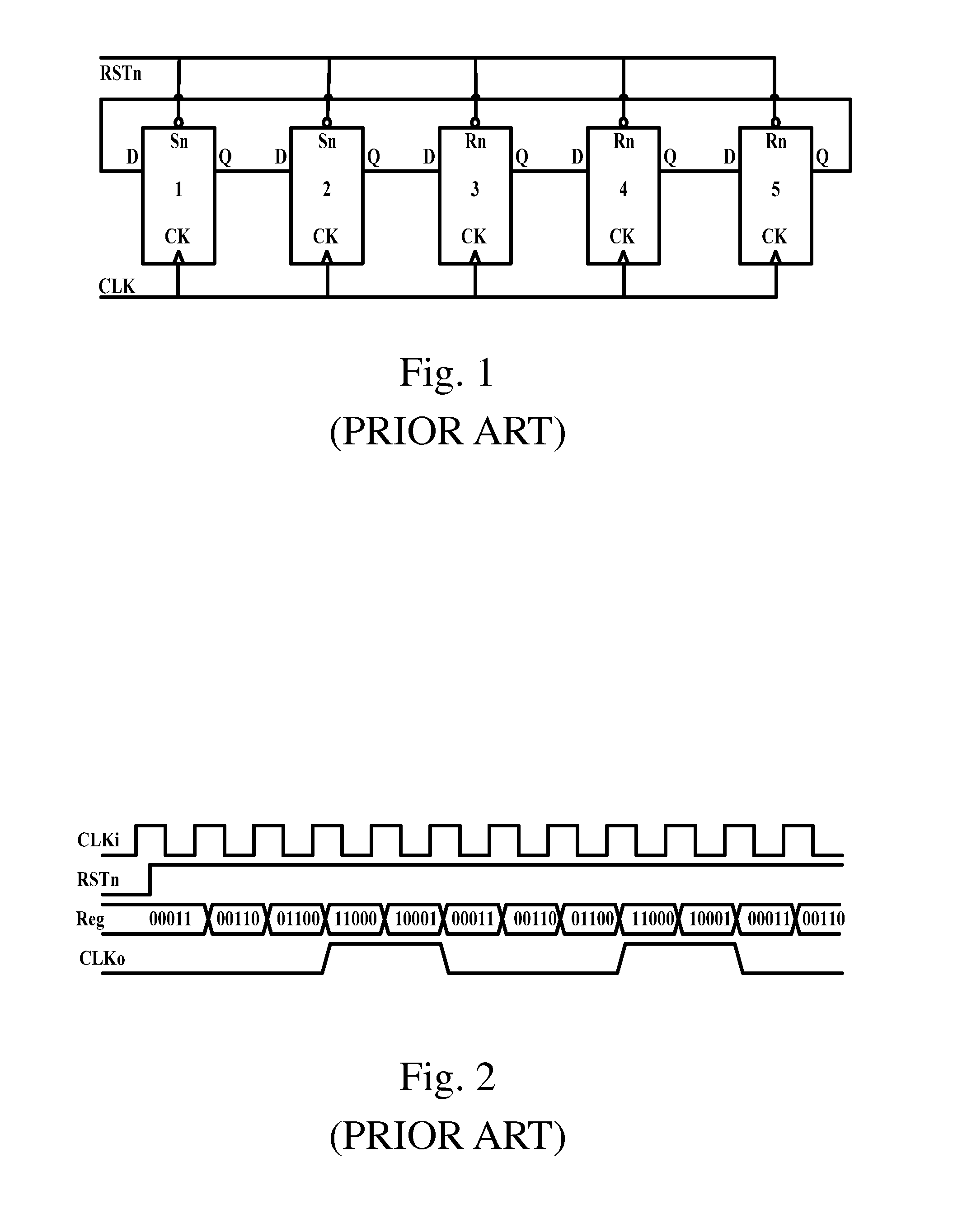
View PDF4 Cites 3 Cited by
  • Summary
  • Abstract
  • Description
  • Claims
  • Application Information

AI Technical Summary

Benefits of technology

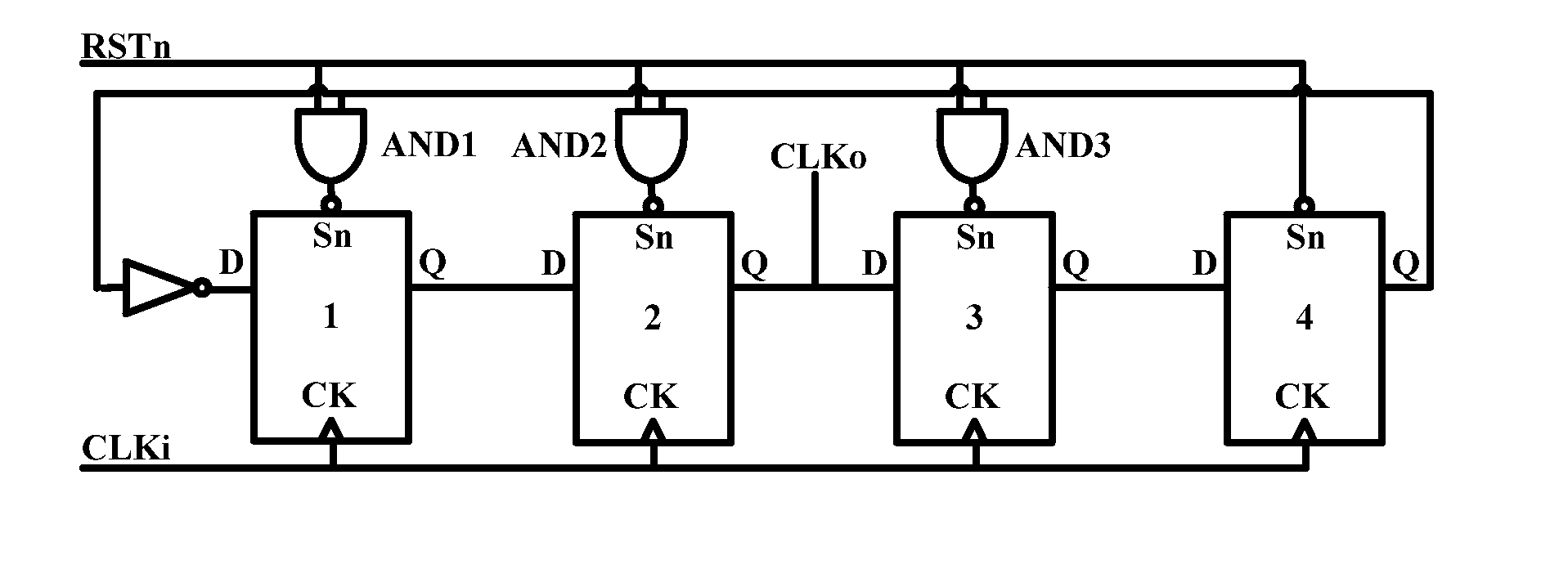
[0014]Compared with the prior art, the shift frequency demultiplier with the automatic reset function of the present invention has the simple structure and is easy to use. Even if the error occurs at the intermediate state, the shift frequency demultiplier can be normally recovered after a period of time, thus ensuring the correctness of the frequency demultiplication.

Problems solved by technology

Compared with the shift frequency demultiplier, the count frequency demultiplier has more complex control logic and can not meet the timing requirements in the high frequency design, thus it is commonly used to design the frequency demultiplier with middle and low frequency clocks.
However, the shift frequency demultiplier has a fatal defect that the quality of the frequency-demultiplied clock entirely depends on the initial state of the register group and the state transition during the operation.
Once the error of the state occurs due to some unexpected reasons, the error of the frequency demultiplication, even the entire error will be directly produced.
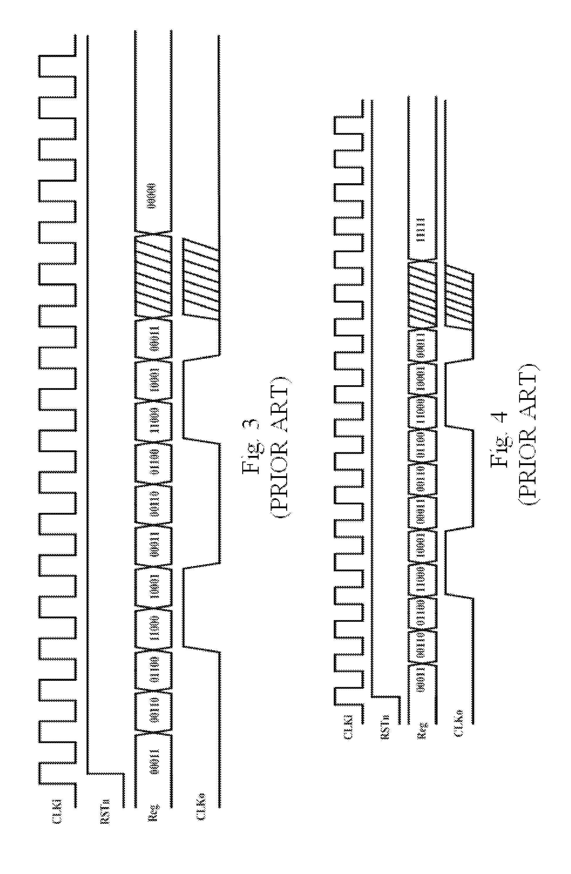
Referring to FIG. 3, if the state of the shift frequency demultiplier is changed to be “0000” due to the reason that the error occurs at the intermediate state, the shift frequency demultiplier can't be normally recovered, thus the error of the shift frequency demultiplication occurs.
Referring to FIG. 4, if the state of the shift frequency demultiplier is changed to be “1111” due to the reason that the error occurs at the intermediate state, the shift frequency demultiplier can't be normally recovered, thus the error of the shift frequency demultiplication occurs.
Referring to FIG. 5, if discontinuous “0” or “1” occurs due to the reason that the error occurs at the intermediate state, the shift frequency demultiplier can't be normally recovered, thus the error of the shift frequency demultiplication occurs.

Method used


Image

  • Shift frequency demultiplier with automatic reset function
  • Shift frequency demultiplier with automatic reset function
  • Shift frequency demultiplier with automatic reset function

Examples


Embodiment Construction

[0026]A shift frequency demultiplier with automatic reset function of the present invention is an N-frequency demultiplication (N>2) shift frequency demultiplier and comprises N-1 registers connected with each other and defined from the first register to the (N-1)th register. Every register has an input end, an output end, a reset end and a clock end. For the registers from the first register to the (N-2)th register, the output end of every register is connected with the input end of the next register adjacent thereto. The output end of the (N-1)th register is connected with the input end of the first register by a reverser. The reset end of the (N-1)th register is connected with a system reset signal end. The system reset signal end logically multiplied by the output end of the (N-1)th register is connected with the reset ends of the registers from the first register to the (N-2)th register, namely, the shift frequency demultiplier comprises N-2 AND gates defined from the first AND...


PUM


Abstract

A shift frequency demultiplier with automatic reset function is N-frequency demultiplication (N>2) and includes N-1 registers connected with each other and defined from a first register to an (N-1)th register. Each of the registers has an input end, an output end, a reset end and a clock end. For the registers from the first register to the (N-2)th register, the output end of every register is connected with the input end of a next register adjacent thereto, the output end of the (N-1)th register is connected with the input end of the first register by a reverser. The reset end of the (N-1)th register is connected with a system reset signal end. The system reset signal end logically multiplied by the output end of the (N-1)th register is connected with the reset ends of the registers from the first register to the (N-2)th register.

Description

BACKGROUND OF THE PRESENT INVENTION[0001]1. Field of Invention[0002]The present invention relates to a shift frequency demultiplier, and more particularly to a shift frequency demultiplier with the automatic reset function.[0003]2. Description of Related Arts[0004]The shift frequency demultiplier and the count frequency demultiplier are two kinds of common frequency demultipliers.[0005]Compared with the shift frequency demultiplier, the count frequency demultiplier has more complex control logic and can not meet the timing requirements in the high frequency design, thus it is commonly used to design the frequency demultiplier with middle and low frequency clocks. The shift frequency demultiplier has much easier control logic and can meet the timing requirements in the high frequency design, thus it is commonly used to design the frequency demultiplier with high frequency clock. However, the shift frequency demultiplier has a fatal defect that the quality of the frequency-demultiplie...

Claims


Application Information

Patent Timeline
Patent Type & Authority Applications(United States)
IPC IPC(8): H03K23/54
CPCH03K23/54H03K21/38
Inventor YANG, XIU
Owner IPGOAL MICROELECTRONICS (SICHUAN) CO LTD
Learn More