
Riveting unit for motor end cover and electric pipe fitting

A motor end cover and riveting technology, applied in the direction of feeding device, positioning device, storage device, etc., can solve the problems of increasing process complexity, reducing riveting efficiency, increasing riveting time consumption, etc.

Active Publication Date: 2018-02-02
南阳防爆(苏州)特种装备有限公司
View PDF6 Cites 6 Cited by
  • Summary
  • Abstract
  • Description
  • Claims
  • Application Information

AI Technical Summary

Problems solved by technology

Although this device can complete the riveting of the combination of pipe fittings and other objects, it needs to carry out end treatment on the pipe fittings first, which increases the complexity of the process. Although the riveting quality is improved to a certain extent, it increases the time consumption of riveting and reduces the riveting efficiency

Method used


Image

  • Riveting unit for motor end cover and electric pipe fitting
  • Riveting unit for motor end cover and electric pipe fitting
  • Riveting unit for motor end cover and electric pipe fitting

Examples


Embodiment Construction

[0044] The technical solutions in the embodiments of the present invention will be clearly and completely described below in conjunction with the accompanying drawings in the embodiments of the present invention. Obviously, the described embodiments are only a part of the embodiments of the present invention, rather than all the embodiments. Based on the embodiments of the present invention, all other embodiments obtained by those of ordinary skill in the art without creative work shall fall within the protection scope of the present invention.

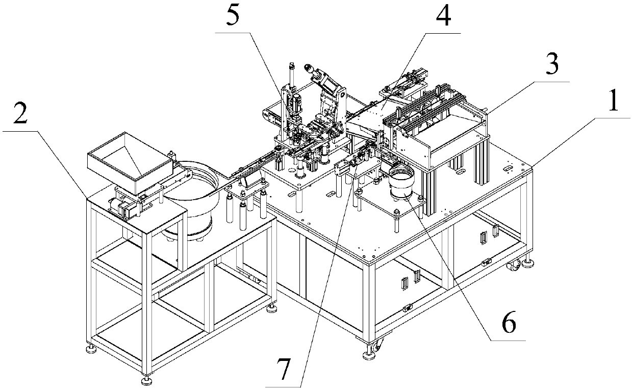
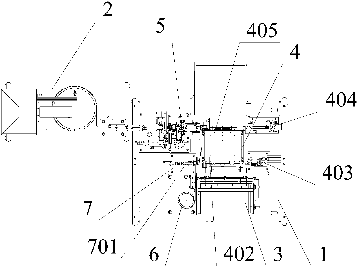
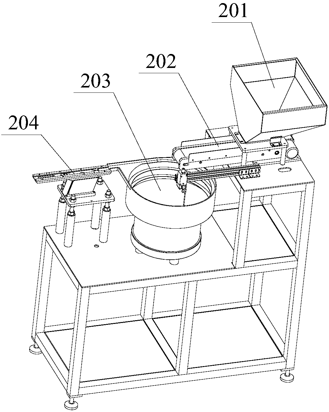
[0045] Such as Figure 1-22 As shown, a riveting equipment for motor end covers and power pipe fittings, such as Figure 1~2 Shown: It includes a chassis 1 and an end cover feeding mechanism 2. The chassis 1 is provided with a power pipe sorting and transferring mechanism for riveting equipment and a directional riveting mechanism 5 for riveting the pipes transferred by the moving mechanism 4 (that is, the present invention Provided is a ...


PUM


Abstract

The invention provides a riveting unit for a motor end cover and an electric pipe fitting. The riveting unit comprises a pipe fitting riveting permanent seat for clamping the pipe fitting, a pipe fitting riveting and punching control mechanism for driving the pipe fitting riveting permanent seat to clamp or loosen the pipe fitting, an end cover riveting permanent seat for fixing the end cover, anend cover riveting and punching control mechanism for driving the end cover riveting permanent seat and a riveting supporting block, wherein the pipe fitting riveting permanent seat comprises a pipe fitting guide permanent seat for fixing the pipe fitting. The riveting unit can realize the accurate abutting joint between the motor end cover and the electric pipe fitting and completes riveting.

Description

Technical field [0001] The present invention relates to the technical field of automatic assembly of power equipment, and more specifically, to a riveting unit for motor end covers and power pipes. Background technique [0002] In the previous riveting of workpieces, it is generally operated manually, but manual operation is easy to make mistakes, which directly affects the service life of the product, and the worker's work efficiency is low, which increases the production cost. The existing riveting machine has a complex structure. The operation is inconvenient and the cost is high. In view of this, it is necessary to improve the existing riveting machine. [0003] Moreover, many products in daily life production (including the production of power equipment) are formed by connecting multiple pipe fittings. At present, there are roughly three ways to connect pipe fittings. One is welding, but the surface of the metal pipe will be deformed and heated during welding. Discoloration, ...

Claims


Application Information

Patent Timeline
IPC IPC(8): B21D39/00B21D43/02B21D43/10B21D43/00B21C51/00
CPCB21C51/00B21D39/00B21D43/003B21D43/02B21D43/10
Inventor 张健
Owner 南阳防爆(苏州)特种装备有限公司
Learn More