
Movable contact piece for switchgear and switchgear with same

A technology of switch devices and moving contacts, applied in the direction of electric switches, contacts, contact surface shape/structure, etc., can solve problems such as experiment failure and product failure

Active Publication Date: 2020-09-15
TCL INT ELECTRICAL HUIZHOU
View PDF5 Cites 0 Cited by
  • Summary
  • Abstract
  • Description
  • Claims
  • Application Information

AI Technical Summary

Problems solved by technology

[0007] Based on this, it is necessary to provide a moving contact piece for a switchgear with good on-off and meeting the standard requirements for the problem that the traditional switchgear is prone to experimental failure or the product is not energized. Switching device for moving contact

Method used


Image

  • Movable contact piece for switchgear and switchgear with same
  • Movable contact piece for switchgear and switchgear with same
  • Movable contact piece for switchgear and switchgear with same

Examples


Embodiment Construction

[0043] In order to make the purpose, technical solution and advantages of the present invention clearer, the following examples are used to describe the movable contact piece for switchgear and the switchgear with it according to the present invention in conjunction with the accompanying drawings. For further details. It should be understood that the specific embodiments described here are only used to explain the present invention, not to limit the present invention.

[0044] It should be noted that when an element is referred to as being “fixed” to another element, it can be directly on the other element or there can also be an intervening element. When an element is referred to as being "connected to" another element, it can be directly connected to the other element or intervening elements may also be present. In contrast, when an element is referred to as being "directly on" another element, there are no intervening elements present. The terms "vertical," "horizontal," ...


PUM


Abstract

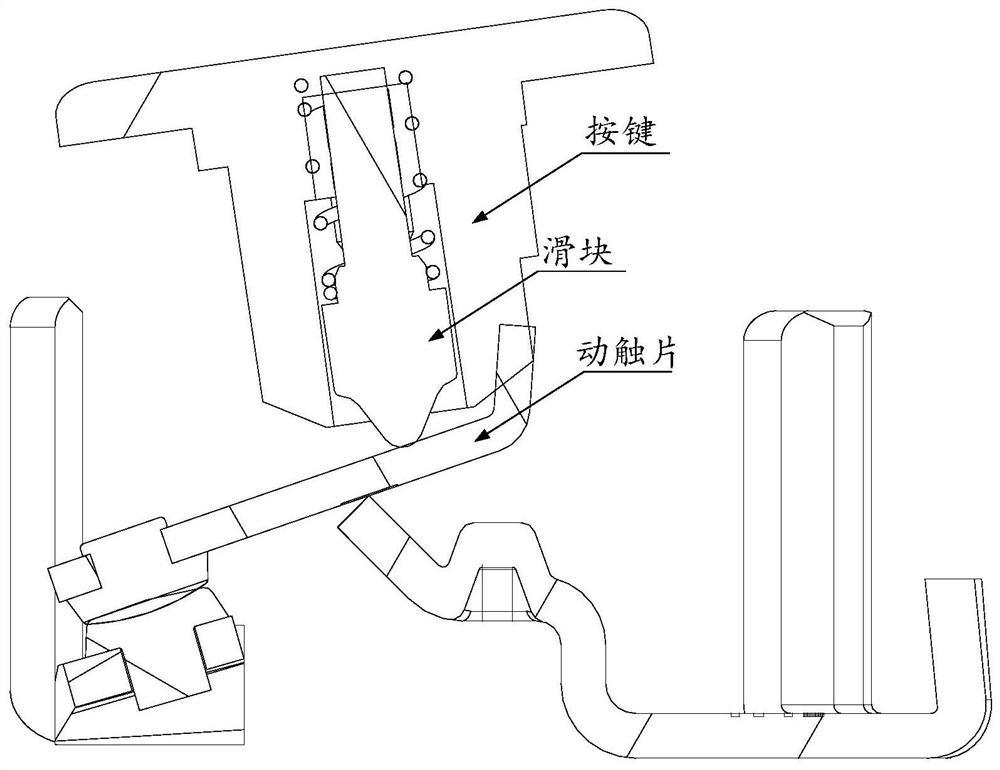
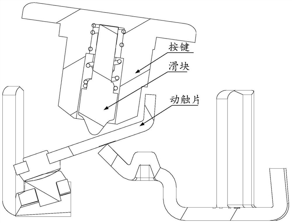
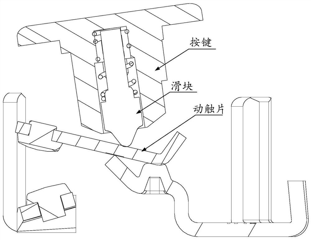
The invention relates to the technical field of electric appliance switches, in particular to a movable contact sheet for a switch device. The movable contact sheet comprises a driving part and a contact part which are connected with each other. The driving part is in an arc-shaped plate shape and is used for being abutted against a sliding block of the switch device. The contact part is arrangedat one end of the driving part and is used for being in contact with a contact of the switch device. The driving part has a first region and a second region. When the contact part is in fixed contactwith a contact point of the switch device, the second area generates a torque on the sliding block of the switch device to enable the sliding block of the switch device to move towards the first area.The driving part of the movable contact sheet is designed in an arc-shaped plate shape, and the driving part has the first area and the second area which are used for being abutted against the sliding block of the switch device. When the contact part is in fixed contact with the contact point, the second area generates a torque on the sliding block to enable the sliding block to move towards thefirst area, so the sliding block is in an instability state and cannot stay in the 'OFF' position, so as to avoid false indication and protect the personal safety of an operator.

Description

technical field [0001] The invention relates to the technical field of electrical switches, in particular to a movable contact piece used for a switch device and a switch device having the same. Background technique [0002] Based on safety considerations, the BS1363 standard requires that when the contacts of the switch remain closed, the drive element of the switch must not stay in the open position. The drive mechanism shall be constructed so that, when operated, the switch can only be held in the positive contact or positive open position. [0003] When testing the safety of a switching device, the force F necessary to close the switch should first be measured, and the force should be applied at the farthest end of the actuating element. The actuating element of the switch is fixed in the contact position and the moving contact piece of the switch pole to be subjected to the severe test shall be mechanically held closed to the contacts. The force exerted on the activat...

Claims


Application Information

Patent Timeline
Patent Type & Authority Patents(China)
IPC IPC(8): H01H1/50H01H1/06
CPCH01H1/06H01H1/50H01H2001/508
Inventor 张小会吉红杰
Owner TCL INT ELECTRICAL HUIZHOU
Learn More