Optical fiber remote end power supply system with safety protection device and implementation method of optical fiber remote end power supply system

A technology for safety protection devices and power supply systems, applied in emergency protection circuit devices, distribution line transmission systems, circuit devices, etc., can solve problems such as skin injuries and fires, and achieve the effect of protecting personal and property safety

Inactive Publication Date: 2017-02-22
南京奥依菲光电科技有限公司
View PDF7 Cites 16 Cited by
  • Summary
  • Abstract
  • Description
  • Claims
  • Application Information

AI Technical Summary

Problems solved by technology

When ordinary optical fibers are used for communication, the transmission power is at the level of milliwatts, which is in the laser safety standard of Class 1 or Class 2 lasers, while the optical power used for optical fiber remote power supply systems is on the order of 500 milliwatts or more, which is in the Class 4 laser

Method used


Image

  • Optical fiber remote end power supply system with safety protection device and implementation method of optical fiber remote end power supply system
  • Optical fiber remote end power supply system with safety protection device and implementation method of optical fiber remote end power supply system
  • Optical fiber remote end power supply system with safety protection device and implementation method of optical fiber remote end power supply system

Examples


Embodiment Construction

[0049] In order to better understand the technical content of the present invention, specific embodiments are given together with the attached drawings for description as follows.

[0050]Aspects of the invention are described in this disclosure with reference to the accompanying drawings, which show a number of illustrated embodiments. Embodiments of the present disclosure are not necessarily intended to include all aspects of the invention. It should be appreciated that the various concepts and embodiments described above, as well as those described in more detail below, can be implemented in any of numerous ways, since the concepts and embodiments disclosed herein are not limited to any implementation. In addition, some aspects of the present disclosure may be used alone or in any suitable combination with other aspects of the present disclosure.

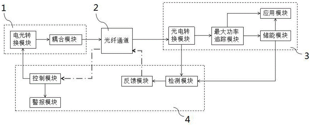
[0051] The invention provides an optical fiber remote power supply system with a safety protection device and a realization m...


PUM


Abstract

The invention provides an optical fiber remote end power supply system with a safety protection device and an implementation method of the optical fiber remote end power supply system. The optical fiber remote end power supply system comprises a source end for converting electric energy into optical energy, a remote end for converting the optical energy into the electric energy for application or storage, an optical fiber channel for transmitting the optical energy and a communication signal between the source end and the remote end, and the safety protection device for monitoring whether the whole optical fiber remote end power supply system normally works or not in real time; the safety protection device comprises a detection module, a feedback module and a control module; the detection module detects an electric signal in a photoelectric conversion module at the remote end in real time; the feedback module processes the detection result of the detection module and sends an alarm signal to the control module when voltage or current is lower than a set value; and the control module stops running of the photoelectric conversion module. According to the optical fiber remote end power supply system, the safety protection measures of the system are completed while optical fiber remote end power supply is achieved; a power supply network is effectively protected; and the fireproof and explosion-proof targets and the target of protecting the person and property safety are achieved.

Description

technical field [0001] The invention relates to the technical field of transmission equipment safety protection, in particular to an optical fiber remote power supply system with a safety protection device and an implementation method thereof. Background technique [0002] Optical fiber remote power supply system is a system that uses optical fiber as the transmission medium to convert electrical energy into optical energy for transmission. Compared with traditional power transmission, the use of optical fiber to transmit energy has the following advantages: (1) It only transmits light and does not conduct electricity, is less affected by electromagnetic interference, is safe and has low loss, and can be used in flammable and explosive places. (2) The transmission medium is light, the volume is small, the source of raw materials is wide, and the corrosion resistance is strong, the service life is long, and the transmission loss of the optical fiber is not affected by the tem...

Claims


Application Information

Patent Timeline
IPC IPC(8): H02J50/30H02J13/00H02H7/26H04B3/54
CPCH02H7/262H04B3/54H02J13/00019Y04S40/121Y02E60/00
Inventor 韦玮刘宁陈晓红
Owner 南京奥依菲光电科技有限公司
Why Eureka
Try Eureka