Engine overspeed protection and control method

An engine overspeed and protection control technology, applied in engine control, combustion engine, machine/engine, etc., can solve problems such as the action of the engine overspeed protection device, affecting the normal use of the engine, and the failure of the protection device, so as to improve reliability and save electricity. , the effect of protecting personal safety

Active Publication Date: 2012-10-10
HEBEI HUABEI DIESEL ENGINE
View PDF5 Cites 17 Cited by
  • Summary
  • Abstract
  • Description
  • Claims
  • Application Information

AI Technical Summary

Problems solved by technology

[0003] There are two types of existing overspeed protection devices: one is that when the engine is working normally, the fuel cut-off solenoid valve is in the energized state; The disadvantage of this method is that when the engine is working normally, sometimes the engine overspeed protection device will operate due to reasons other than overspeed, which will affect the normal use of the engine; When the controller detects that the engine is overspeeding, the fuel cut-off solenoid valve is energized. The disadvantage of this method is that the engine is in normal working condition most of the time, so the fuel cut-off solenoid valve will not be energized for a long time. If the user fails to check and deal with it in time, once an overspeed fault occurs, the engine will be damaged due to the failure of the protection device, and more importantly, unnecessary harm will be caused to the user
In addition, once the overspeed protection controller fails due to circuit, program and other reasons, the protection device will also fail, and it is usually difficult for the operator to find these failures, resulting in unimaginable consequences

Method used


Image

  • Engine overspeed protection and control method
  • Engine overspeed protection and control method

Examples


Embodiment Construction

[0022] The present invention will be described in further detail below in conjunction with the accompanying drawings.

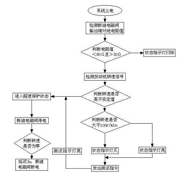
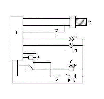
[0023] An engine overspeed protection control system includes a controller 1 , a rotational speed sensor 2 , a test button 3 , a storage battery 7 , an over relay 5 , a fuel cutoff solenoid valve 6 , a state indicator light 4 and a test indicator light 10 .

[0024] The rotational speed sensor is used to detect the rotational speed of the engine in real time, and transmit the detected rotational speed of the engine to the controller in real time. The fuel cut-off solenoid valve is connected to the output end of the controller, and the relay is set between the fuel cut-off solenoid valve and the controller. The relay is used to control the power on and off of the fuel cut-off solenoid valve under the instructions issued by the controller, and further makes the fuel cut-off solenoid valve act , cut off the engine fuel. The test button is used to start the syst...


PUM


Abstract

The invention discloses an engine overspeed protection and control method, which is based on an engine overspeed protection and control system and particularly comprises the following steps: A, detecting the working condition of a fuel cut electromagnetic valve; B, detecting the engine speed by a speed sensor; C, automatically starting protection in case of overspeed; D, starting power-off protection for the engine; E, detecting the working condition of the speed sensor; and F, manually detecting whether or not the system is normal. The engine overspeed protection and control method can randomly detect all inactive elements in the system during the normal operation of the engine, so that failure in circuits and elements of the system can be detected timely; when the failure occurs, an alarm can be issued timely and displayed to the operator, so as to remind the operator of timely maintenance; therefore, the safety performance of the engine is greatly improved, and the personal safety of the user can be efficiently protected.

Description

technical field [0001] The invention relates to the field of engine protection, in particular to a protection system and method for overspeed protection of the engine when the engine is overspeed. Background technique [0002] During the driving process of the car, the phenomenon of engine overspeed often occurs, which not only damages the engine, but also is extremely unsafe for users. The overspeed protection device is a device that automatically cuts off the fuel supply of the engine and makes the engine exit the overspeed state when the engine overspeeds due to technical failure, thereby protecting the engine. At present, overspeed protection devices have been widely used in generator sets and other fields, and are generally realized through the following methods: the controller collects the signal of the engine speed sensor, and once it detects that the engine speed exceeds the limit value, the controller outputs a control signal to the fuel cutoff solenoid valve throug...

Claims


Application Information

Patent Timeline
Patent Type & Authority Applications(China)
IPC IPC(8): F02D41/22
CPCY02T10/40
Inventor 勾志勇商海昆申杰何剑丰许明胜董长龙王砚冰
Owner HEBEI HUABEI DIESEL ENGINE
Why Eureka
Try Eureka