
Data transmission via energy supply lines in battery pack systems

A technology for energy supply lines and battery packs, applied in battery circuit devices, distribution line transmission systems, battery/battery traction, etc. Effect

Active Publication Date: 2020-11-13
ROBERT BOSCH GMBH
View PDF1 Cites 0 Cited by
  • Summary
  • Abstract
  • Description
  • Claims
  • Application Information

AI Technical Summary

Problems solved by technology

This results in strong signal attenuation and distortion during data communication
Although a topology for data transmission can be provided in principle via power supply lines, this topology cannot be used over large distances due to interference

Method used


Image

  • Data transmission via energy supply lines in battery pack systems
  • Data transmission via energy supply lines in battery pack systems
  • Data transmission via energy supply lines in battery pack systems

Examples


Embodiment Construction

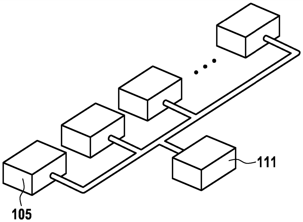
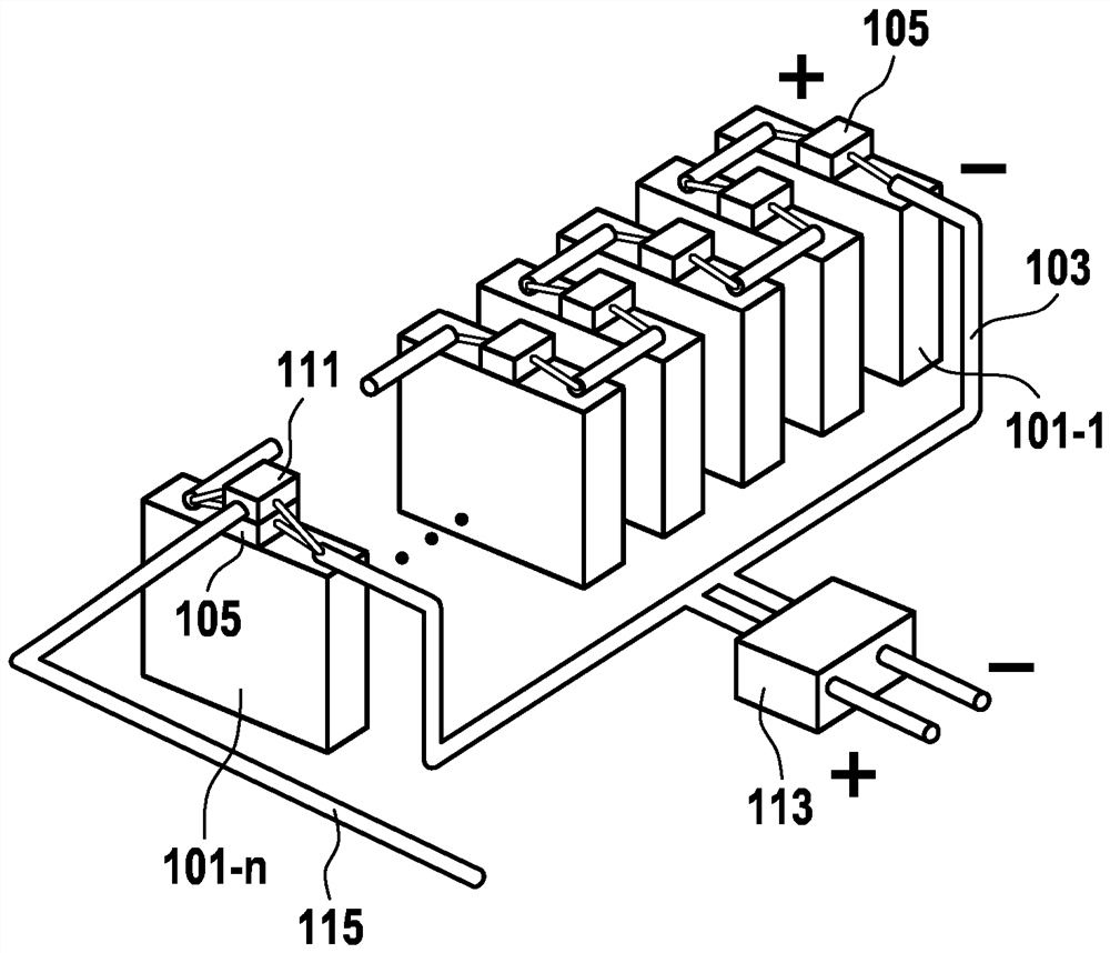
[0029] Figure 1a A battery system 100 with a plurality of battery cells 101 - 1 , . . . , 101 -n is shown. The battery system 100 is, for example, the battery system 100 of an electric or hybrid vehicle with lithium-ion battery cells, which is used to supply the drive with energy. For the function of the battery system 100, the status data of the individual battery cells 101-1, ..., 101-n can be analyzed, for example for load balancing (charging) between the individual battery cells 101-1, ..., 101-n. Balance) to control the battery cells 101-1, ..., 101-n.

[0030] The battery cells 101-1, . . . , 101-n are connected in series via a power supply line 103 for transmitting battery power in order to obtain an output voltage as high as possible. The battery system 100 includes outwardly directed terminals 113 in order to interconnect the battery system 100 with a drive train (inverter) or other batteries as modules.

[0031] Each of the battery cells 101-1, . Sending means 10...


PUM


Abstract

The invention relates to a battery system (100) having a plurality of battery cells (101-1, 101-2, 101-3) via a power supply line for transmitting battery power (103) to connect to each other, the battery cells respectively include: receiving means (107) for receiving data through the power supply line (103); and for sending data through the power supply line (103) Data sending means (109).

Description

technical field [0001] The invention relates to a battery system with a plurality of battery cells and a method for transmitting data within the battery system, wherein the plurality of battery cells are connected via a power supply line for transmitting battery power connected to each other. Background technique [0002] In a battery system with a plurality of battery cells, data can only be transmitted poorly via the power supply line, since devices connected to the power supply line cause disturbances and interference during the data transmission. This results in strong signal attenuation and distortion during data communication. Although in principle a topology for data transmission can be provided via power lines, this topology cannot be used over large distances due to interference. [0003] The printed document WO 2014 / 103008 describes a battery system with a communication unit for wirelessly communicating battery information. Contents of the invention [0004] T...

Claims


Application Information

Patent Timeline
Patent Type & Authority Patents(China)
IPC IPC(8): B60L3/00B60L3/12B60L50/64H01M10/48H02J7/00H02J13/00H04B3/54H04Q9/00
CPCB60L50/64B60L58/22B60L58/21B60L50/51B60L3/0046B60L3/12H01M10/482H02J7/0047H04B3/548H04Q9/00B60L2240/549B60L2240/547B60L2240/545H01M2220/20H04B2203/5445H04Q2209/30H02J7/0013H02J13/00007Y02T10/70Y02E60/10
Inventor P.尼克尔
Owner ROBERT BOSCH GMBH
Learn More