
Self-locking cable hooker suspension device

A technology of cable hooks and suspension devices, which is applied in the direction of overhead lines/cable equipment, manipulators, manufacturing tools, etc., and can solve problems such as the inability to self-adaptively lock the cable hook, the failure of the jaws to clamp the cable hook, and the unstable fixing of the cable hook, etc. , to achieve the effect of simple structure, convenient operation and convenient portability

Pending Publication Date: 2018-02-09
SUZHOU VOCATIONAL UNIV
View PDF1 Cites 8 Cited by
  • Summary
  • Abstract
  • Description
  • Claims
  • Application Information

AI Technical Summary

Problems solved by technology

[0002] During the construction or use of the communication cable, it often slips from the high steel strand due to the unstable fixing of the cable hook. At this time, the construction personnel on the ground need to use auxiliary tools to rehang the cable hook back to the steel strand. In order to restore the communication cable to the original state of use, the existing application number is 201610168750.9, a device for hanging the cable hook, which is locked by locking the key into the stepped slot, which belongs to the step lock. When the diameter of the cable hook If it is too large, the key will not fit into the stepped slot. When the size of the cable hook is too small, the jaws will not be able to clamp the cable hook. When the size of the cable hook is between the two gears, the jaws will The cable hook cannot be clamped well at the bottom, and the cable hook may fall off during the hanging process, and it cannot self-adaptively lock the cable hooks of various diameters

Method used


Image

  • Self-locking cable hooker suspension device
  • Self-locking cable hooker suspension device
  • Self-locking cable hooker suspension device

Examples


Embodiment Construction

[0017] The present invention will be further described in detail below in conjunction with the accompanying drawings and specific embodiments.

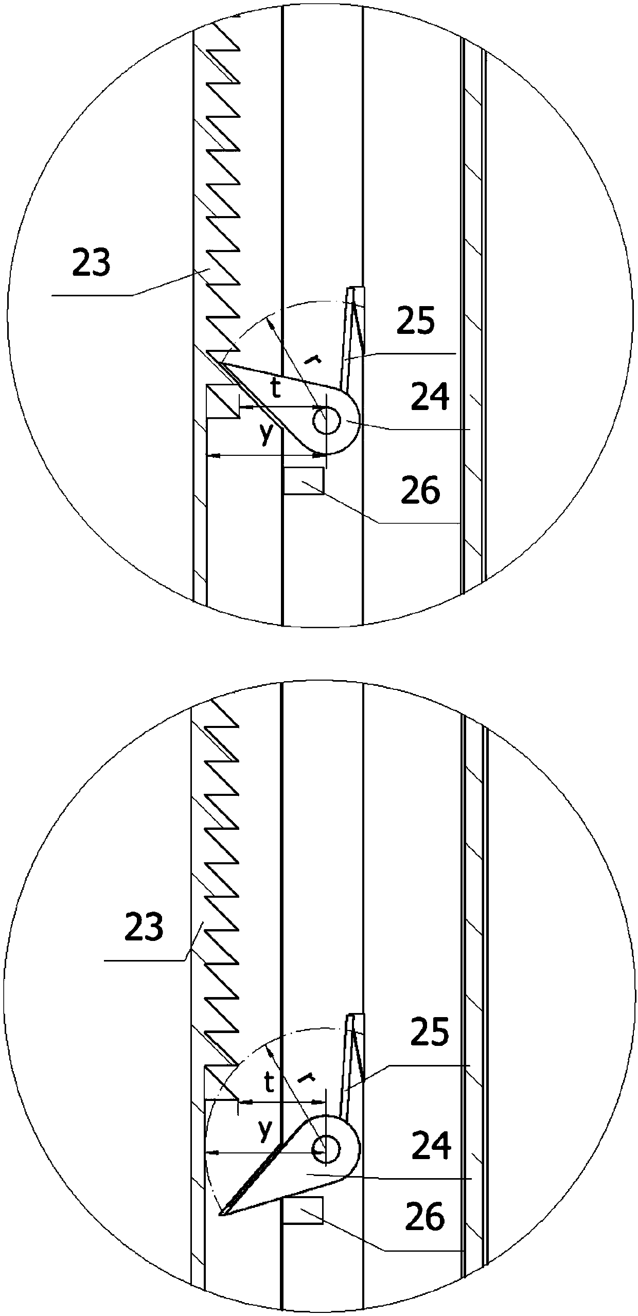
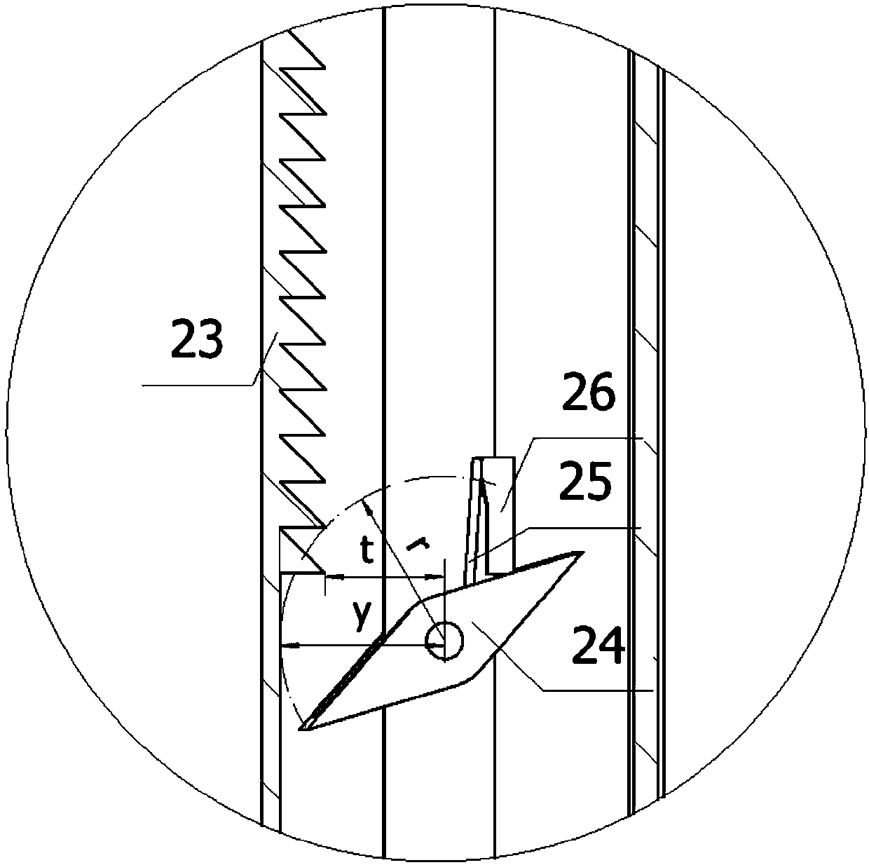
[0018] attached Figure 1-5 For the self-locking cable hook suspension device of the present invention, the structure of the device comprising the suspension cable hook is as follows: figure 2 As shown, it includes a jaw part, a rod part and a handle part connected in sequence, the jaw part includes a fixed jaw 2 and a movable jaw 1, and both the fixed jaw 2 and the movable jaw 1 have certain toughness, and the rod part includes The telescopic rod 3 and the pull rod 8, the handle part includes a fixed handle 4 and a movable handle 5; the upper part of the telescopic rod 3 is provided with a fixed jaw 2 and a movable jaw 1, and the lower part is provided with a fixed handle 4 and a movable handle 5; the fixed jaw 2 It is arc-shaped with the movable jaw 1, which is convenient for clamping the cable hook; the lower end of the fixed jaw...


PUM


Abstract

The invention discloses a self-locking cable hooker suspension device. The self-locking cable hooker suspension device comprises a vice jaw part, a rod part and a handle part which are connected in sequence, wherein the vice jaw part comprises a fixed vice jaw and a movable vice jaw; the rod part comprises an extension rod and a pull rod; the handle part comprises a fixed handle and a movable handle; the fixed vice jaw is fixed at the upper end of the extension rod; the movable vice jaw is articulated with the fixed vice jaw; the lower part of the movable vice jaw is articulated with the pullrod in the extension rod; the fixed handle is fixed at the lower end of the extension rod; the movable handle is articulated with the pull rod, and meanwhile, the head of the movable handle is articulated with the fixed handle; and a self-locking mechanism causing the vice jaw part to lock by itself is arranged at one end, close to the vice jaw part, of the interior of the extension rod. The self-locking cable hooker suspension device has the beneficial effects that the self-locking mechanism is driven by pinching the vice jaw part so as to cause the vice jaw part to lock by itself, so that the self-locking cable hooker suspension device can be suitable for cable hookers with different diameters; and the extension rod is adjustable in length so as to be suitable for cable steel strands different in height.

Description

technical field [0001] The invention relates to a communication cable construction auxiliary tool, in particular to a self-locking cable hook suspension device. Background technique [0002] During the construction or use of the communication cable, it often slips from the high steel strand due to the unstable fixing of the cable hook. At this time, the construction personnel on the ground need to use auxiliary tools to rehang the cable hook back to the steel strand. In order to restore the communication cable to the original state of use, the existing application number is 201610168750.9, a device for hanging the cable hook, which is locked by locking the key into the stepped slot, which belongs to the step lock. When the diameter of the cable hook If it is too large, the key will not fit into the stepped slot. When the size of the cable hook is too small, the jaws will not be able to clamp the cable hook. When the size of the cable hook is between the two gears, the jaws w...

Claims


Application Information

Patent Timeline
Patent Type & Authority Applications(China)
IPC IPC(8): B25J1/04H02G1/04
CPCH02G1/04B25J1/04
Inventor 张跃赵祥文李大臣李建蓉赵海燕郭南初
Owner SUZHOU VOCATIONAL UNIV
Learn More