
Imaging method and imaging device

An imaging method and imaging technology, applied in the field of geological exploration, can solve problems such as low imaging accuracy, and achieve the effect of improving imaging accuracy

Active Publication Date: 2018-02-09
PETROCHINA CO LTD
View PDF5 Cites 2 Cited by
  • Summary
  • Abstract
  • Description
  • Claims
  • Application Information

AI Technical Summary

Problems solved by technology

[0011] Embodiments of the present invention provide an imaging method and device to solve the problem of low imaging accuracy of undulating land in the prior art

Method used


Image

  • Imaging method and imaging device
  • Imaging method and imaging device
  • Imaging method and imaging device

Examples


Embodiment Construction

[0042] In order to make the object, technical solution and advantages of the present invention clearer, the present invention will be described in further detail below in conjunction with the embodiments and accompanying drawings. Here, the exemplary embodiments and descriptions of the present invention are used to explain the present invention, but not to limit the present invention.

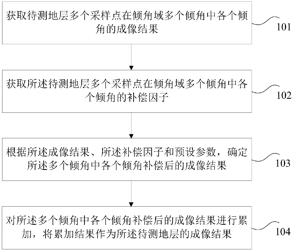
[0043] Considering the problem of low imaging accuracy of the undulating surface, the inventor proposes to analyze the imaging results of the formation to be measured in the dip domain, and use the compensation factor calculated in the dip domain to perform illumination compensation on the imaging results of the formation to be measured. The method of accumulating the imaging results of each dip angle after compensation, and using the accumulative results as the imaging results of the formation to be measured. Specifically, an imaging method is proposed in this embodiment, such as figure 1 As ...


PUM


Abstract

The invention provides an imaging method and an imaging device. The method comprises steps: an imaging result of each inclination angle in multiple inclination angles in an inclination angle domain ofmultiple sampling points of a to-be-tested formation is acquired; the compensation factor for each inclination angle in multiple inclination angles in the inclination angle domain of multiple sampling points of the to-be-tested formation is acquired; according to the imaging result, the compensation factor and a preset parameter, the imaging result after compensation of each inclination angle inmultiple inclination angles is determined; the imaging results after compensation of each inclination angle in multiple inclination angles are accumulated, and the accumulated result is used as an imaging result of the to-be-tested formation. In the embodiment of the invention, the imaging result of the to-be-tested formation is analyzed in the inclination angle domain which more meets an underground wave field propagation law, the compensation factor is used to compensate the imaging result, the imaging results after compensation of the inclination angles are finally accumulated as the imaging result of the to-be-tested formation, the problem of low imaging precision caused due to shielding on the wave field by undulating surface wave field scattering is solved, and the undulating surfaceimaging precision is improved.

Description

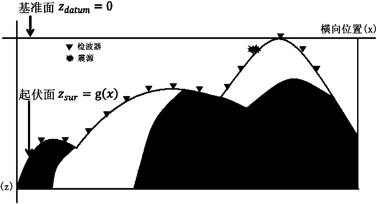
technical field [0001] The invention relates to the technical field of geological exploration, in particular to an imaging method and device. Background technique [0002] The seismic migration imaging may be a depth-domain migration image obtained after seismic data migration processing. The quality of the migration image can affect the subsequent geological interpretation, thus affecting the identification of oil and gas reservoirs. For areas with complex underground structure and complex surface, elevation static correction technology can be used to solve the influence of undulating surface on migration imaging. However, this method assumes that the surface is consistent, and it can be applied to the situation where the surface is less undulating, the lateral change of the low-velocity zone is slow, and the reflections of the shallow, medium and deep underground layers are almost vertically incident on the surface when passing through the low-velocity zone. For areas wi...

Claims


Application Information

Patent Timeline
Patent Type & Authority Applications(China)
IPC IPC(8): G01V1/28
CPCG01V1/28
Inventor 叶月明李立胜刘午牛王启迪邵萌珠
Owner PETROCHINA CO LTD
Learn More