Ray tracing type ultrasonic Lamb wave defect tomographic imaging method

A technology of ray tracing and imaging methods, which is applied in the analysis of solids using sonic/ultrasonic/infrasonic waves, material analysis using sonic/ultrasonic/infrasonic waves, and analysis of materials, etc. It can solve the problem that the specific size and contour cannot be estimated very accurately.

Active Publication Date: 2015-04-22
TSINGHUA UNIV
View PDF5 Cites 13 Cited by
  • Summary
  • Abstract
  • Description
  • Claims
  • Application Information

AI Technical Summary

Problems solved by technology

Chinese patent literature discloses a "guided wave on-line detection method for steel storage tank bottom plate". Reconstructing the tomographic image can quickly realize the comprehensive detection and defect analysis of

Method used


Image

  • Ray tracing type ultrasonic Lamb wave defect tomographic imaging method
  • Ray tracing type ultrasonic Lamb wave defect tomographic imaging method
  • Ray tracing type ultrasonic Lamb wave defect tomographic imaging method

Examples


Embodiment Construction

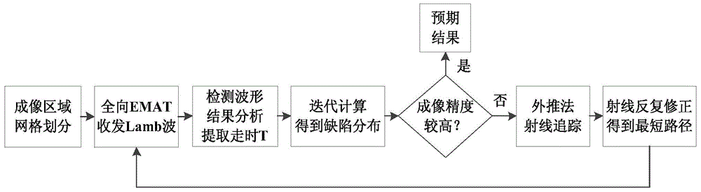
[0033] The essence of the method proposed by the present invention is to establish a brand-new ray tracing (Ray Tracing, RT) iterative algorithm model, and combine it with the TOF cross-hole tomography technology. Alternately, iteratively solves the problem, and corrects the ray paths in the positive problem to obtain a more realistic defect distribution. Below in conjunction with embodiment, the present invention is further described:

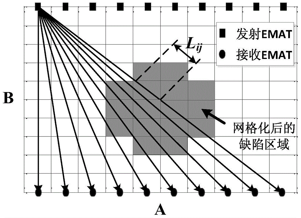
[0034] Step 1: Take the aluminum plate to be tested with a thickness of 1-5mm, and select a rectangular area with an area of ​​A×B on the upper surface as the imaging area for the experiment, where A and B are positive real numbers, and both are greater than 30mm. A standard artificial corrosion pit defect with a diameter greater than or equal to 30 mm and a depth of 1-5 mm is processed in the area. The imaging area is then divided into N 1 ×N 2 small grids (i.e. N 1 ×N 2 pixels). M transmitting EMATs (electromagnetic acoustic transducer...


PUM

PropertyMeasurementUnit
Diameteraaaaaaaaaa

Abstract

The invention belongs to the field of nondestructive testing, and relates to a ray tracing type ultrasonic Lamb wave defect tomographic imaging method, first, a to-be-measured material imaging area is divided into a plurality of small grids, and the same amount of emission EMAT (electro-magnetic acoustic transducer) and receiving EMAT are arranged on both sides of the area, then all emission ends are allowed to excite A0 mode Lamb wave, all receiving ends at the opposite side receive meanwhile, analysis results of all tested waveforms are extracted, the corresponding time is recorded, the slowness and defect distribution of every grids are determined by use of combined iterative reconstruction algorithm, the obtained defect distribution is used as a known condition for establishment of a RT extrapolation formula, by use of the extrapolation method, a ray path is gradually traced and corrected, and the ray path is gradually traced and corrected repeatedly until high imaging precision is obtained by calculation. The a ray tracing type ultrasonic Lamb wave defect tomographic imaging method avoids the problem of low imaging precision of a traditional TOF cross hole tomographic imaging method based on straight ray theory, is accurate, efficient and fast to calculate, provides an important basis for improving the defect imaging precision, and has broad application prospects.

Description

technical field [0001] The invention relates to a ray-tracing ultrasonic Lamb wave defect tomography method, which belongs to the technical field of non-destructive testing. Background technique [0002] Using ultrasonic Lamb wave defect tomography technology can quickly and effectively obtain specific information such as the contour and size of the defect. This technology inherits many advantages of traditional ultrasonic Lamb wave detection. Lamb wave travel time (Time-of-flight, TOF, refers to the propagation time of Lamb wave between transceiver pairs) cross-aperture tomography technology, which uses linear transducer arrays for fan beam projection and imaging, is a kind of Efficient and fast tomography method based on iterative method. The traditional Lamb wave TOF trans-hole tomography is based on the straight ray theory, that is, it is assumed that the Lamb wave ray still propagates in a straight line after encountering a defect during the propagation process. Howe...

Claims


Application Information

Patent Timeline
IPC IPC(8): G01N29/06G06F19/00
CPCG01N29/069G01N29/0672G01N29/07G01N29/2412G01N2291/0427
Inventor 黄松岭王坤赵伟李世松魏争
Owner TSINGHUA UNIV
Why Eureka
Try Eureka