
A ray-tracing ultrasonic lamb wave defect tomography method

A technology of ray tracing and imaging methods, which is applied in the analysis of solids using sound waves/ultrasonic waves/infrasonic waves, the use of sound waves/ultrasonic waves/infrasonic waves for material analysis, and material analysis. It can solve the problems that specific dimensions and contours cannot be estimated accurately. , to achieve the effect of avoiding low imaging precision, accurate calculation, and broad application prospects

Active Publication Date: 2017-06-30
TSINGHUA UNIV
View PDF5 Cites 0 Cited by
  • Summary
  • Abstract
  • Description
  • Claims
  • Application Information

AI Technical Summary

Problems solved by technology

Chinese patent literature discloses a "guided wave on-line detection method for steel storage tank bottom plate". Reconstructing the tomographic image can quickly realize the comprehensive detection and defect analysis of the tank floor, but this technology is limited to the matrix transformation theory, and can only determine the location and severity of the defect, but cannot achieve the specific size and outline. very accurate estimate

Method used


Image

  • A ray-tracing ultrasonic lamb wave defect tomography method
  • A ray-tracing ultrasonic lamb wave defect tomography method
  • A ray-tracing ultrasonic lamb wave defect tomography method

Examples


Embodiment Construction

[0034] The essence of the method proposed by the present invention is to establish a brand-new iterative algorithm model of Ray Tracing (RT), and combine it with TOF cross-hole tomography technology, integrate the advantages of both, and solve problems through positive and negative problems The solution is repeated alternately, and the ray path in the positive problem is corrected to obtain a more realistic defect distribution. The present invention will be further described below in conjunction with embodiment:

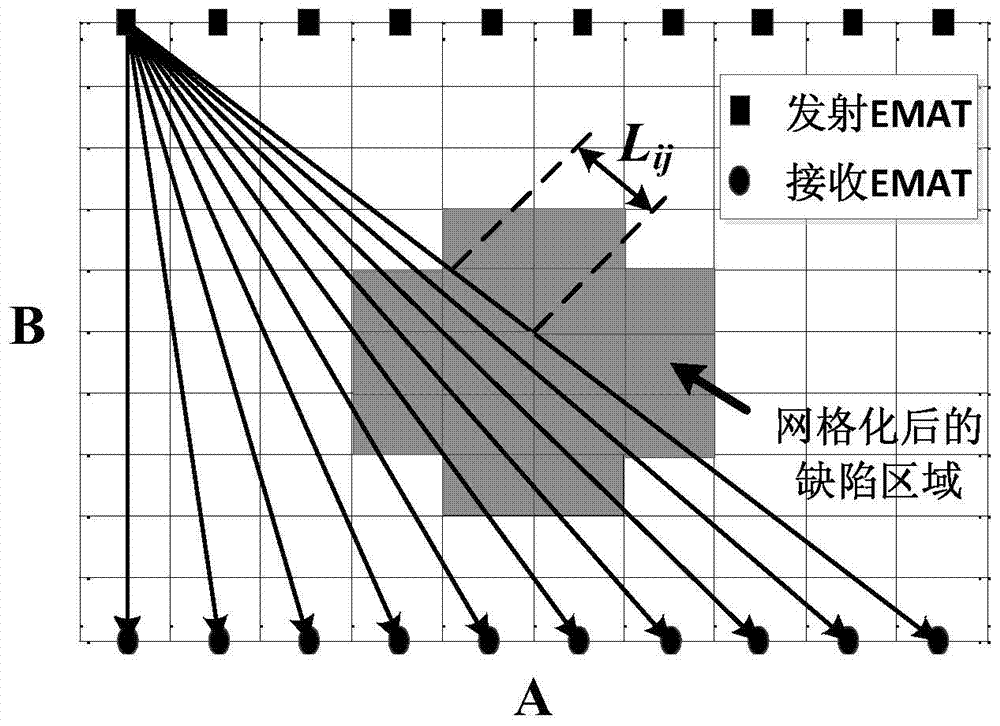
[0035] Step 1: Take the aluminum plate to be tested with a thickness of 1-5mm, and select a rectangular area with an area of ​​A×B on the upper surface as the imaging area for the experiment, where A and B are positive real numbers and both are greater than 30mm. Process a standard artificial corrosion pit defect with a diameter greater than or equal to 30 mm and a depth of 1 to 5 mm in the area. The imaging region is then divided into N 1 ×N 2 small grids (i.e. N...


PUM

PropertyMeasurementUnit
diameteraaaaaaaaaa
thicknessaaaaaaaaaa
diameteraaaaaaaaaa

Abstract

Disclosed are a method and a device for testing a defect based on an ultrasonic Lamb wave tomography. The method includes: partitioning an imaging area of a material to be tested into grids; exciting electromagnetic acoustic transducers for emitting to emit Lamb waves with a A0 mode in all directions, and electromagnetic acoustic transducers for receiving to receive the Lamb waves; obtaining a time-frequency analysis result and recording time-of-flights of testing waves; determining a first slowness of each grid to obtain a first defect area; establishing an extrapolation formula according to the first defect area, and iterating the extrapolation formula to trace and revise paths of the Lamb waves until a better imaging precision is obtained.

Description

technical field [0001] The invention relates to a ray-tracing ultrasonic Lamb wave defect tomography method, which belongs to the technical field of nondestructive testing. Background technique [0002] The specific information such as the outline and size of the defect can be obtained quickly and effectively by using the ultrasonic Lamb wave defect tomography technology. This technology inherits many advantages of traditional ultrasonic Lamb wave detection. Lamb wave travel time (Time-of-flight, TOF, refers to the propagation time of Lamb wave between the transmitting and receiving transducer pairs) cross-aperture tomography technology, using linear transducer array for fan beam projection and imaging, is a kind of An efficient and fast tomography method based on an iterative method. Traditional Lamb wave TOF trans-hole tomography is based on the straight ray theory, which assumes that the Lamb wave ray still propagates along a straight line after encountering a defect du...

Claims


Application Information

Patent Timeline
Patent Type & Authority Patents(China)
IPC IPC(8): G01N29/06G06F19/00
CPCG01N29/069G01N29/0672G01N29/07G01N29/2412G01N2291/0427
Inventor 黄松岭王坤赵伟李世松魏争
Owner TSINGHUA UNIV
Learn More