
Supporting device used for bottom of pile driver

A technology of support device and pile driver, which is applied in sheet pile wall, construction, infrastructure engineering and other directions, can solve the problems of shaking of support device, low flexibility, insufficient device stability, etc., and achieves high safety performance and height adjustment. flexible effects

Pending Publication Date: 2018-02-16
HUBEI ENG INST
View PDF4 Cites 6 Cited by
  • Summary
  • Abstract
  • Description
  • Claims
  • Application Information

AI Technical Summary

Problems solved by technology

[0002] The pile driver is a mechanical equipment used to drive piles and build foundations. During the piling process, the stability of the pile driver needs to be fully guaranteed, and the way to ensure the stability of the pile driver is to use a stable support device for the bottom of the pile driver. But now Some support devices used at the bottom of the pile driver still have certain defects during use. Because the pile driver needs continuous impact, the support device will shake accordingly, which will easily lead to insufficient stability of the device. In order to ensure stable support, The support height of the device cannot be adjusted freely, and there is a defect of low flexibility

Method used


Image

  • Supporting device used for bottom of pile driver
  • Supporting device used for bottom of pile driver
  • Supporting device used for bottom of pile driver

Examples


Embodiment Construction

[0017] The preferred embodiments of the present invention will be described in detail below in conjunction with the accompanying drawings, so that the advantages and features of the present invention can be more easily understood by those skilled in the art, so as to define the protection scope of the present invention more clearly.

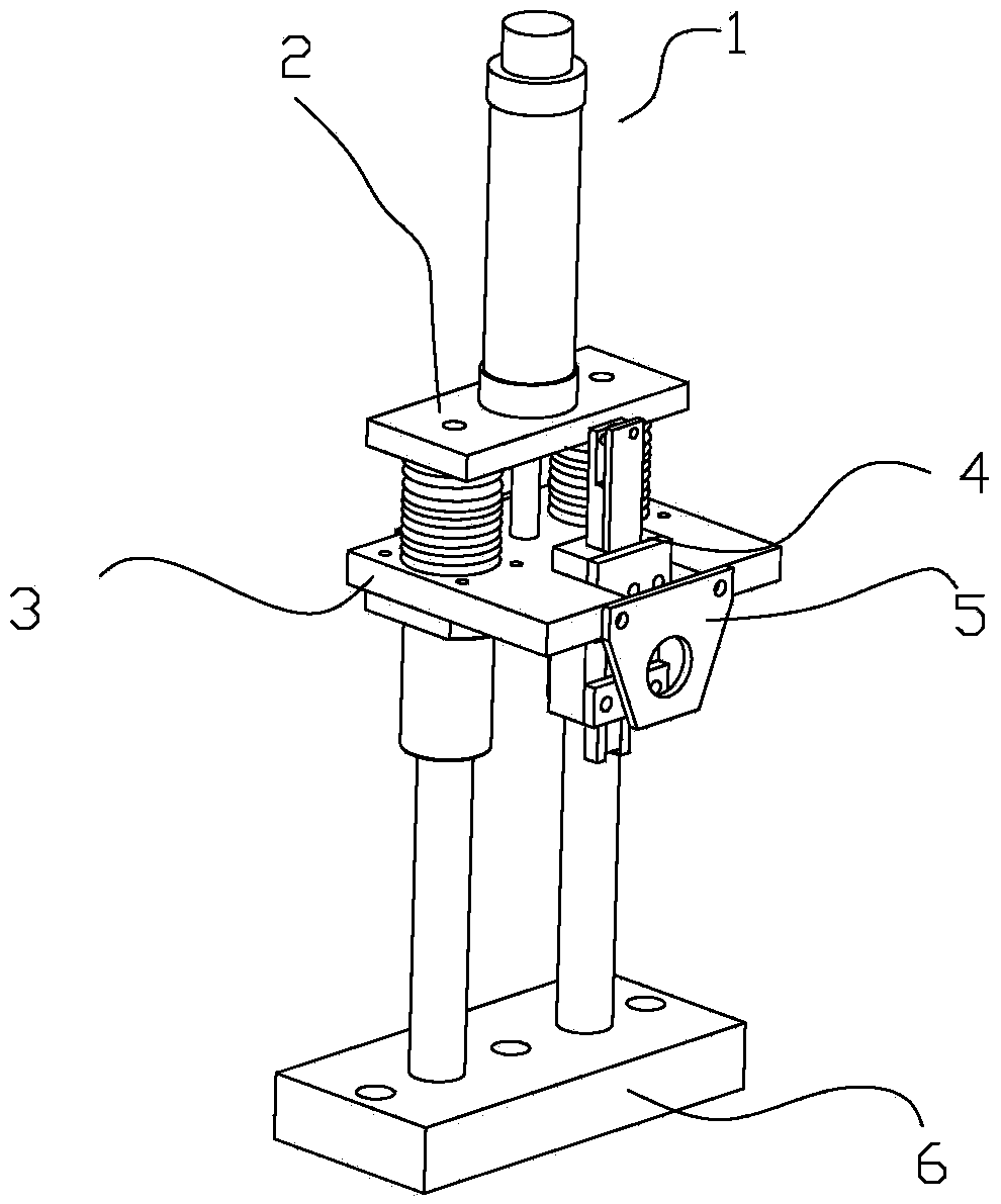
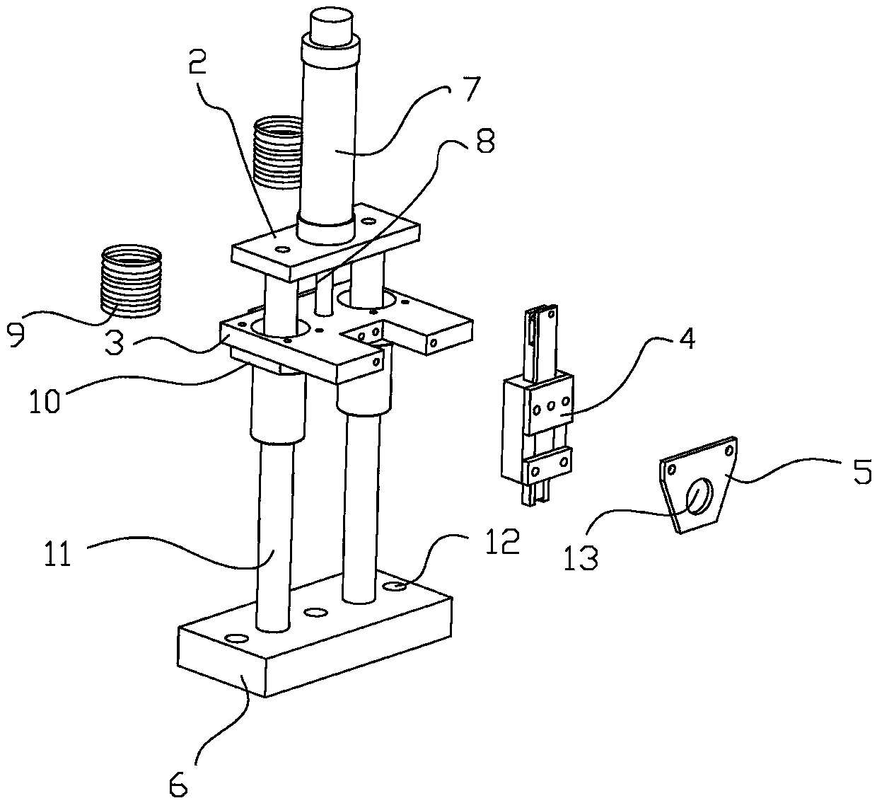
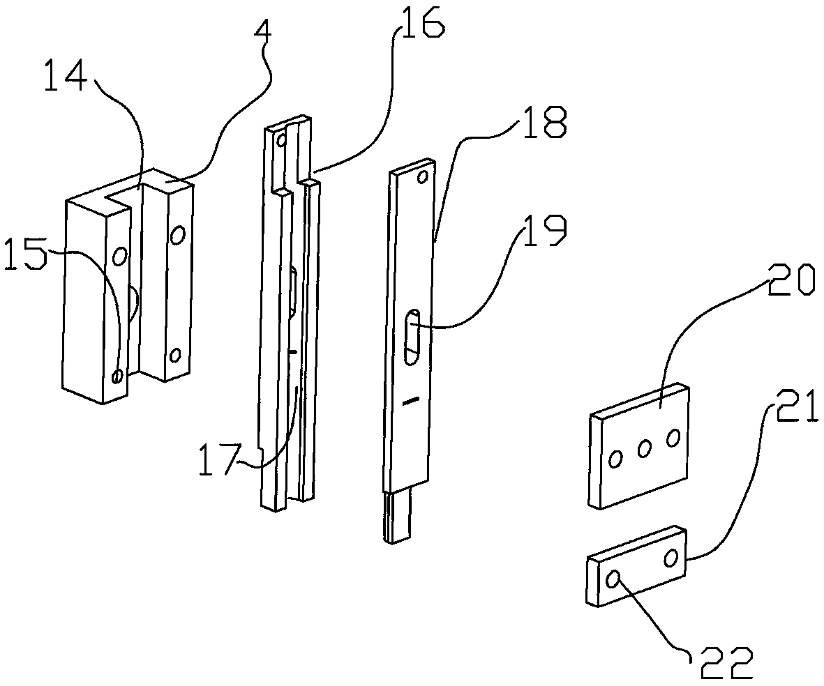
[0018] like Figure 1 to Figure 3 As shown, the supporting device 1 for the bottom of the pile driver includes a top seat 2, a middle plate 3, a top block 4 and a base 6, a vertical connecting rod 7 is welded on the top of the top seat 2, and the top seat 2. The bottom is fixedly connected to the middle plate 3 through a connecting column 8. The top block 4 is installed on one side of the middle plate 3. A card slot 14 is provided in the middle of the side wall of the top block 4, and the upper and lower ends of the top block 4 are provided on the side walls. Both are provided with two nail holes 15, and a clamping block 16 is clamped inside the ...


PUM


Abstract

The invention discloses a supporting device used for the bottom of a pile driver. The supporting device comprises a top base, a middle plate, a top block and a base. A vertical connection rod is welded to the top of the top base. The bottom of the top base is fixedly connected with the middle plate through a connection column. The top block is installed on one side of the middle plate. A clampinggroove is formed in the middle portion of the side wall of the top block. An insertion hole is formed in the middle portion of the side plate. A bottom plate is installed at the bottom of the middle plate. Two telescopic supporting columns are connected in the bottom plate in a penetrating manner. The top ends of the telescopic supporting columns are fixedly connected to the bottom of the top base. The base is installed at the bottoms of the telescopic supporting columns. Multiple screw holes are formed in the base. The portions, between the top base and the middle plate, of the supporting columns are sleeved with two springs. The effect of shock resistance and pressure reduction can be achieved through the good elastic property of the springs, and therefore it is ensured that when the pile driver operates, the device can still conduct stable supporting.

Description

technical field [0001] The present invention relates to a support device, more precisely a support device for the bottom of a pile driver. Background technique [0002] The pile driver is a mechanical device used to drive piles and build foundations. During the piling process, the stability of the pile driver needs to be fully guaranteed, and the way to ensure the stability of the pile driver is to use a stable support device for the bottom of the pile driver. But now Some support devices used at the bottom of the pile driver still have certain defects when they are in use. Because the pile driver needs continuous impact, the support device will shake accordingly, which will easily lead to insufficient stability of the device. In order to ensure stable support, The support height of the device cannot be adjusted freely, and there is a defect of low flexibility. Contents of the invention [0003] The invention mainly solves the technical problems existing in the prior art,...

Claims


Application Information

Patent Timeline
Patent Type & Authority Applications(China)
IPC IPC(8): E02D7/16
CPCE02D7/165
Inventor 胡江平张瀛尹康立武
Owner HUBEI ENG INST
Learn More