Krah pipeline well

A pipeline well and carat tube technology, applied in the pipeline field, can solve problems such as dim light and waste of physical strength, and achieve the effect of ensuring safety and saving physical energy

Pending Publication Date: 2018-02-16
JIANGXI LIDA PLASTIC PIPE IND CO LTD
6 Cites 0 Cited by

AI-Extracted Technical Summary

Problems solved by technology

[0003] Most of the existing pipeline wells are underground, the light in the well is relatively dim, and most of them use escalators to...

Abstract

The invention discloses a Krah pipeline well which comprises a main pipe, a conveying device and a branched pipe. The branched pipe is arranged on the side wall of the main pipe and communicated withthe main pipe, the conveying device is arranged on the inner side of the main pipe and comprises a supporting frame, a connecting plate, a rack, two sliding rails, a U-shaped plate, a servo motor, a driving gear and a treading frame, the supporting frame comprises a side plate and a transverse plate which is fixedly connected with the inner wall of the main pipe, the rack and the sliding rails arefixed on one side of the side plate, the two sliding rails are symmetrically distributed on two corresponding sides of the rack, two ends of the U-shaped plate are mounted on the sliding rails on thetwo sides of the rack respectively, the servo motor is fixed on one side of the U-shaped plate, and an output shaft of the servo motor penetrates the U-shaped plate. Compared with escalators of conventional pipeline wells, the Krah pipeline well has the advantages that safety of a user can be ensured, and physical stamina of the user is saved.

Application Domain

Artificial islandsUnderwater structures

Technology Topic

ServoPipe +3

Image

  • Krah pipeline well
  • Krah pipeline well
  • Krah pipeline well

Examples

  • Experimental program(1)

Example Embodiment

[0013] The technical solutions in the embodiments of the present invention will be clearly and completely described below in conjunction with the accompanying drawings in the embodiments of the present invention. Obviously, the described embodiments are only a part of the embodiments of the present invention, rather than all the embodiments. Based on the embodiments of the present invention, all other embodiments obtained by those of ordinary skill in the art without creative work shall fall within the protection scope of the present invention.
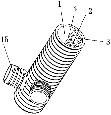
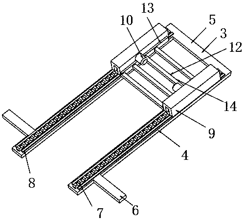
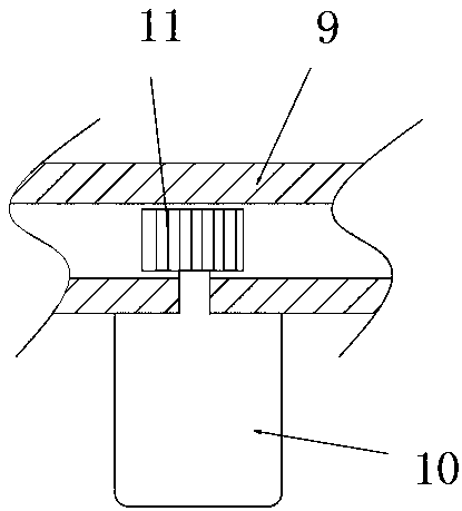
[0014] See Figure 1-3 , The present invention provides a technical solution: a carat pipe well, including a main pipe 1, a conveying device 2, and a branch pipe 15. The side wall of the main pipe 1 is provided with a branch pipe 15, and the branch pipe 15 is in communication with the main pipe 1. A conveying device 2 is provided on the inner side, and the conveying device 2 includes a supporting frame 3, a connecting plate 6, a rack 7, a sliding rail 8, a U-shaped plate 9, a servo motor 10, a driving gear 11 and a foot frame 12. The frame 3 includes a side plate 4 and a horizontal plate 5. The horizontal plate 5 is fixedly connected to the inner wall of the main pipe 1. Both ends of the horizontal plate 5 are welded with side plates 4, and the end of the side plate 4 away from the horizontal plate 5 passes The connecting plate 6 is fixedly connected to the inner wall of the main pipe 1, a rack 7 and a sliding rail 8 are fixed on one side of the side plate 4, and the two sliding rails 8 are symmetrically distributed on the corresponding two sides of the rack 7. The U-shaped plate The two ends of 9 are respectively mounted on the slide rails 8 on both sides of the rack 7, a servo motor 10 is fixed on one side of the U-shaped plate 9 and the output shaft of the servo motor 10 passes through one side of the U-shaped plate 9 It is fixedly connected with the rotation center of the driving gear 11, and the connection between the output shaft of the servo motor 10 and the U-shaped plate 9 is rotationally connected through a bearing. The driving gear 11 meshes with the rack 7 and the U-shaped plate 9 A foot stand 12 is installed.
[0015] The footrest frame 12 includes a side board 13 and a support board 14, and there are several support boards 14 at equal intervals. The two ends of the support board 14 are respectively fixed with side boards 13, and the side board 13 is far away from the support board. One side of 14 is fixedly connected to the U-shaped plate 9.
[0016] The surface of the support plate 14 is provided with anti-slip patterns.
[0017] Working principle: When the carat pipe well needs to go down, firstly, the driving gear 11 is driven to rotate through the output shaft of the servo motor 10. Since the driving gear 11 and the rack 7 mesh with each other, the driving gear 11 will drive the U-shaped plate 9, servo The motor 10 and the step frame 12 move along the slide rail 8 together. The two slide rails 8 are symmetrically distributed on the corresponding two sides of the rack 7 to ensure the stable operation of the step frame 12. Compared with the traditional pipeline well escalator, Not only can the safety of the user be guaranteed, but also the physical energy of the user can be saved.
[0018] It should be noted that in this article, relational terms such as first and second are only used to distinguish one entity or operation from another entity or operation, and do not necessarily require or imply one of these entities or operations. There is any such actual relationship or order between. Moreover, the terms "include", "include" or any other variants thereof are intended to cover non-exclusive inclusion, so that a process, method, article or device including a series of elements not only includes those elements, but also includes those that are not explicitly listed Other elements of, or also include elements inherent to this process, method, article or equipment.
[0019] Although the embodiments of the present invention have been shown and described, those of ordinary skill in the art can understand that various changes, modifications, and substitutions can be made to these embodiments without departing from the principle and spirit of the present invention. And variations, the scope of the present invention is defined by the appended claims and their equivalents.

PUM

no PUM

Description & Claims & Application Information

We can also present the details of the Description, Claims and Application information to help users get a comprehensive understanding of the technical details of the patent, such as background art, summary of invention, brief description of drawings, description of embodiments, and other original content. On the other hand, users can also determine the specific scope of protection of the technology through the list of claims; as well as understand the changes in the life cycle of the technology with the presentation of the patent timeline. Login to view more.

Similar technology patents

Parking braking control device and method

InactiveCN103496360Aprevent movementensure safety
Owner:GREAT WALL MOTOR CO LTD

Mobile phone shielding device for driver

InactiveCN101364814Aensure safetyFacilitate normal communication
Owner:动力新跃(北京)汽车科技有限公司

Classification and recommendation of technical efficacy words

  • save energy
  • ensure safety

Micro-combustor

InactiveCN102183019AReduce heat losssave energy
Owner:HUAZHONG UNIV OF SCI & TECH

Wireless charging device in car travelling

InactiveCN106945565Asave energyreduce electricity supply
Owner:SHANGHAI UNIVERSITY OF ELECTRIC POWER

High accuracy non-contact tri-dimensional facial type measuring device

InactiveCN101105389Aensure safetylow cost
Owner:中国人民解放军第二炮兵装备研究院第四研究所

Intelligent charger with output voltage changing function

Owner:SHENZHEN SIECOM COMM TECH DEV CO LTD
Why Eureka
Try Eureka