Eureka AIR delivers breakthrough ideas for toughest innovation challenges, trusted by R&D personnel around the world.

Contact protection type relay

A relay and contact technology, applied in the field of contact protection relays, can solve problems such as contact damage, lifting, and interference with the normal use of contacts, and achieve the effects of improving performance, avoiding interference, and prolonging service life

Active Publication Date: 2018-02-16
SANYOU CORP LTD
View PDF5 Cites 0 Cited by
  • Summary
  • Abstract
  • Description
  • Claims
  • Application Information

AI Technical Summary

Problems solved by technology

[0002] As the "automatic switch" in the circuit, the relay is already one of the essential basic components in many electronic devices; most of the relays include drive components and contact components. In actual use, the drive components are used to drive the contact components to realize the contact components. The conduction or disconnection of the relay; most of the contact components of the existing relay are exposed. During the assembly process of the relay, other parts of the relay will touch the contact, resulting in damage to the contact; in addition, during the use of the relay, Other accessories of the relay will also interfere with the normal use of the contacts, which is not conducive to the improvement of the performance of the relay

Method used


Image

  • Contact protection type relay
  • Contact protection type relay
  • Contact protection type relay

Examples


Embodiment Construction

[0028] In order to facilitate the understanding of those skilled in the art, the present invention will be further described below in conjunction with the embodiments and accompanying drawings, and the contents mentioned in the implementation modes are not intended to limit the present invention.

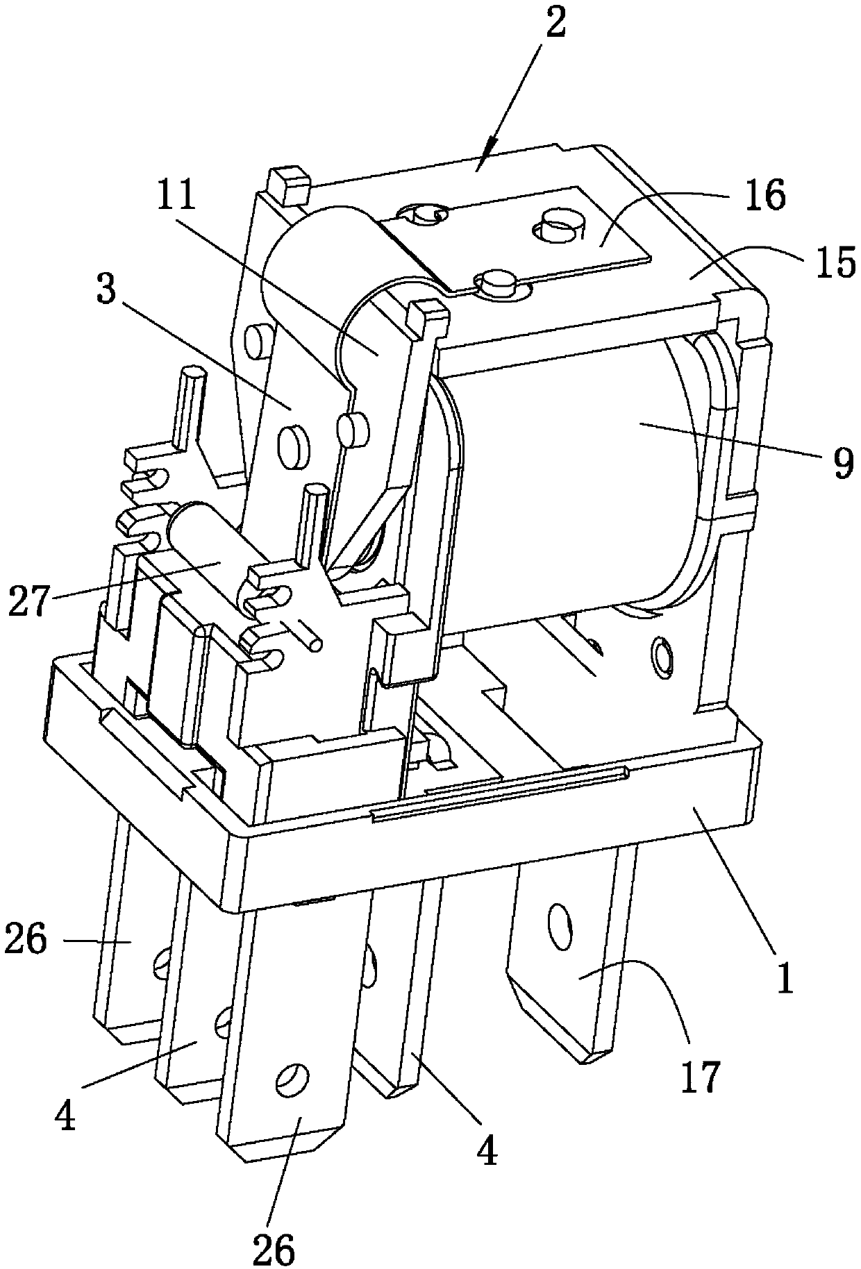
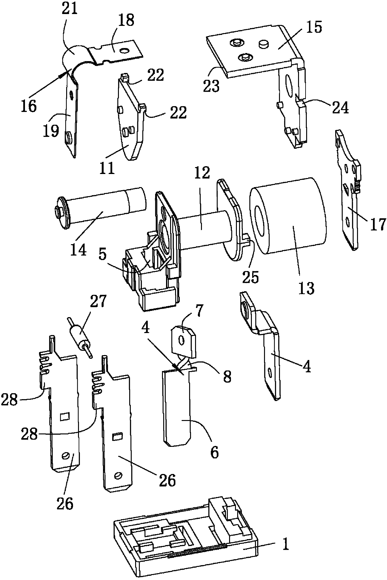
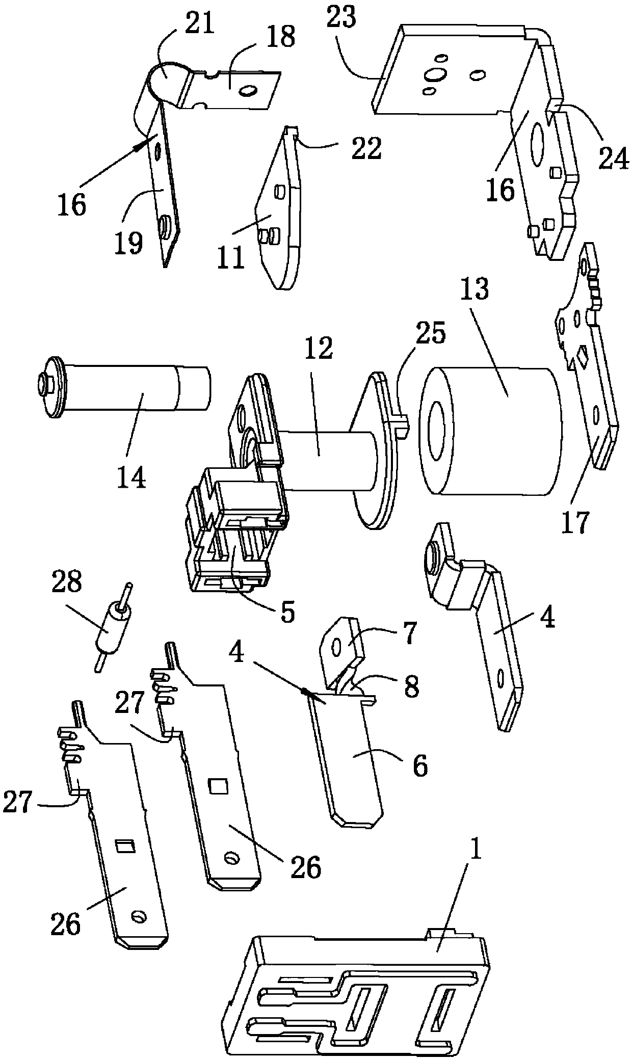
[0029] see Figure 1 to Figure 3 As shown, a contact protection relay of the present invention includes a base 1, a driving mechanism 2 installed on the base 1, a moving terminal 3 and a static terminal 4, and the driving mechanism 2 is used to drive the moving terminal 3 to move back and forth ; The base 1 is provided with an accommodating groove 5, the static terminal 4 is provided with a static contact (not labeled in the figure) protruding into the accommodating groove 5, and the moving terminal 3 is provided with a protruding into the accommodating groove 5 The moving contact (not labeled in the figure) inside, the driving mechanism 2 is used to drive the moving contact to cond...


PUM


Abstract

The invention relates to the technical field of relays, and particularly discloses a contact protection type relay, which comprises a base, a driving mechanism arranged on the base, a movable terminaland a static terminal. The base is provided with an accommodating groove. The static terminal is provided with a static contact which protrudes into the accommodating groove. The movable terminal isprovided with a movable contact which protrudes into the accommodating groove. The driving mechanism is used for driving the movable terminal to drive the movable contact to move back and forth so asto realize the on / off state of the movable contact with the static contact. According to the invention, the movable contact and the static contact are arranged in the accommodating groove. In this way, the movable contact and the static contact are protected by the side walls of the accommodating groove. During the assembling process of the relay, other accessories of the relay are prevented fromtouching the movable contact or the static contact, so that the service life of the contacts is prolonged. During the usage process of the relay, the interference caused by the normal use of other accessories of the relay to the contacts is avoided. The usage performance of the relay is improved.

Description

technical field [0001] The invention relates to the technical field of relays, and in particular discloses a contact protection relay. Background technique [0002] As the "automatic switch" in the circuit, the relay is already one of the essential basic components in many electronic devices; most of the relays include drive components and contact components. In actual use, the drive components are used to drive the contact components to realize the contact components. The conduction or disconnection of the relay; most of the contact components of the existing relay are exposed. During the assembly process of the relay, other parts of the relay will touch the contact, resulting in damage to the contact; in addition, during the use of the relay, Other accessories of the relay will also interfere with the normal use of the contacts, which is not conducive to the improvement of the performance of the relay. Contents of the invention [0003] In order to overcome the shortcom...

Claims


Application Information

Patent Timeline
IPC IPC(8): H01H50/64H01H50/56H01H50/14H01H50/44
CPCH01H50/14H01H50/44H01H50/56H01H50/64
Inventor 刘振伟
Owner SANYOU CORP LTD
Why Eureka
Eureka Blog
Learn More