Power supply plug device

A technology of power supply plugging and power supply tank, which is applied to the parts of the connection device, coupling device, circuit, etc., can solve the problems of unstable power supply of the power supply tank, reduced service life of electrical equipment, electric shock accidents of young children, etc. To achieve the effect of simple operation steps of power connection and power off, reduce electric shock accidents, and avoid electric shock accidents

Inactive Publication Date: 2018-02-16
罗亚香
View PDF0 Cites 4 Cited by
  • Summary
  • Abstract
  • Description
  • Claims
  • Application Information

AI Technical Summary

Problems solved by technology

[0002] At present, the use of electrical equipment needs to be plugged into the power supply tank before it can be used. However, the existing sockets are basically installed in the wall, and the power supply tank on the socket is directly connected to the power supply. The plug can be plugged directly into the power supply slot to be powered on. Although this plug-in method is very convenient to operate, the power supply slot will always be powered on, and the power supply slot is not equipped with protective parts that can be covered. If there are young children at home Inserting fingers or metal rods into the power supply groove under the condition of supervision will cause electric shock accidents for young children, and in severe cases, it will cause life-threatening danger to young children. In addition, due to the length of the wire between the plug and the electrical equipment Not one, when in use, the wires are often placed randomly. If someone accidentally kicks and hits the wires by mistake, it will cause a sudden power failure of the electrical equipment, so that the service life of the electrical equipment will be reduced. In serious cases It will also directly cause the burning of the electrical equipment, so there is a big safety hazard in the plugging method between the existing plug and the power supply tank, and the power supply of the power supply tank is unstable.

Method used


Image

  • Power supply plug device
  • Power supply plug device
  • Power supply plug device

Examples


Embodiment Construction

[0019] The preferred embodiments of the present invention will be described in detail below in conjunction with the accompanying drawings, so that the advantages and features of the present invention can be more easily understood by those skilled in the art, so as to define the protection scope of the present invention more clearly.

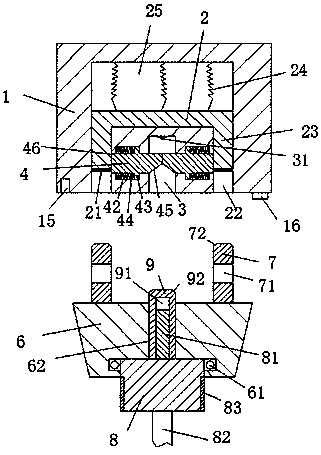
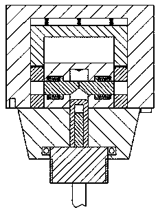
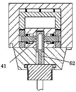
[0020] refer to Figure 1-4 The power supply plug-in device shown includes a power supply body 1 and a plug 6 mated with the power supply body 1. The power supply body 1 includes two slots 22 arranged symmetrically on the left and right and opened forward, and arranged on the Between the two slots 22 and the power supply slot 3 opening forward, the rear end wall of the power supply slot 3 is provided with a power supply contact 31 connected to the power supply, and the rear ends of the two slots 22 communicate with a Sliding groove 25, in which the sliding block 2 that can slide back and forth is provided, and the rear end surface of the sliding ...


PUM


Abstract

The invention discloses a power supply plug-in device, which comprises a power supply body and a plug cooperating with the power supply body. Between the power supply slots with opening forward, the rear end wall of the power supply slots is provided with power supply contacts connected with the power supply, and the rear ends of the two slots are connected with sliding slots, in the sliding slots The sliding block that can slide back and forth is provided, the overall structure of the present invention is simple, the production cost is low, the power supply is safe and stable, and the operation steps of power connection and power off are relatively simple, which effectively reduces the electric shock accidents in the existing life and guarantees the safety of people's lives , It can also avoid the occurrence of power failure accidents of electrical equipment caused by accidental kicking and bumping, and reduce the burnout rate of electrical equipment, which is suitable for popularization and use.

Description

technical field [0001] The invention relates to the technical field of power supply, in particular to a power supply plug-in device. Background technique [0002] At present, the use of electrical equipment needs to be inserted into the power supply tank before it can be used. However, the existing sockets are basically installed in the wall, and the power supply tank on the socket is directly connected to the power supply. The plug can be plugged directly into the power supply slot to be powered on. Although this plugging method is very convenient to operate, the power supply slot will always be powered on, and the power supply slot is not equipped with protective parts that can be covered. If there are young children at home Inserting fingers or metal rods into the power supply groove under supervision will cause electric shock accidents for young children, and in severe cases, it will cause life-threatening danger to young children. In addition, due to the length of the w...

Claims


Application Information

Patent Timeline
Patent Type & Authority Applications(China)
IPC IPC(8): H01R13/447H01R13/639
CPCH01R13/447H01R13/639
Inventor 陈柯
Owner 罗亚香
Why Eureka
Try Eureka