Upper limb rehabilitation trainer with energy accumulators

A technology of accumulator and training device, which is applied to gymnastics equipment, sports accessories, etc., can solve the problems of inability to adjust the distance, strength and speed of the rehabilitation training device, and achieve the goal of improving the quality of rehabilitation, improving comfort, and stimulating interest in rehabilitation. Effect

Inactive Publication Date: 2018-02-23
ANYANG INST OF TECH
View PDF4 Cites 8 Cited by
  • Summary
  • Abstract
  • Description
  • Claims
  • Application Information

AI Technical Summary

Problems solved by technology

[0002] With the continuous development of rehabilitation, the functions of rehabilitation training devices tend to be diversified. At present, one side of the upper limb of the patient can move independently to drive the other side of the upper limb rehabilitation training device. Most of the rehabilitation training devices cannot adjust the distance of the rehabilitation training device. The shoulder width of each patient Different, the rehabilitation trainer needs to be designed with multiple specifications. At the same time, due to the influence of the weight of the rehabilitation training mechanism during the lifting and lowering of the patient's upper limbs, the strength and speed change significantly. In addition, how the patient loads the adjustable damping during the rehabilitation training process is a lot of rehabilitation. What the trainer cannot achieve

Method used


Image

  • Upper limb rehabilitation trainer with energy accumulators
  • Upper limb rehabilitation trainer with energy accumulators
  • Upper limb rehabilitation trainer with energy accumulators

Examples


Embodiment Construction

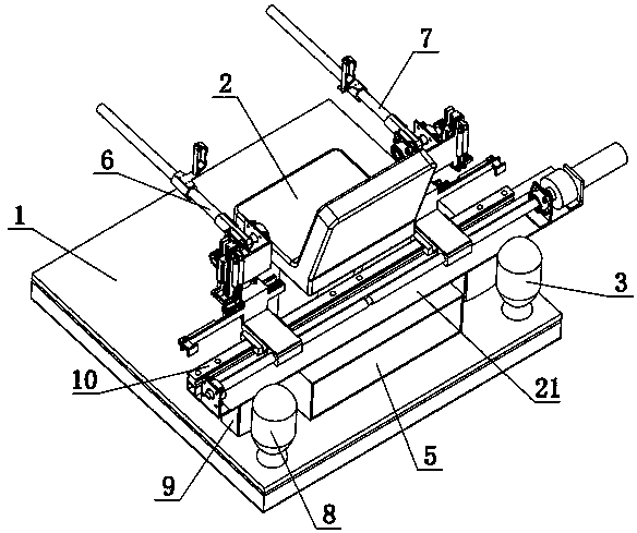
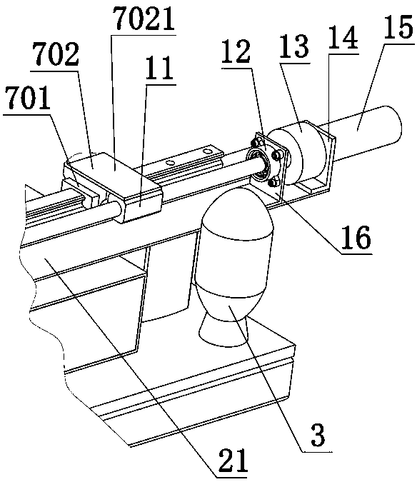
[0033] combine Figure 1-11 , a kind of upper limb rehabilitation trainer with accumulator of the present invention comprises base 1, seat 2, right accumulator 3, hydraulic control system 4, control box 5, left upper limb mechanism 6, right upper limb mechanism 7 , left accumulator 8, support 9, linear guide rail 10, right nut 11, bearing housing one 12, coupling 13, motor frame 14, motor 15, bearing frame one 16, left nut 17, bearing frame two 18 , Bearing housing 2 19, lead screw 20, and supporting plate 21, define the left and right directions according to the orientation when a person sits on the seat, so as to describe the application. The seat 2 is fixed on the base 1, and the seat 2 is an electric lifting seat, that is, a connecting part between the seat and the base is provided with an electric lifting column, and the hydraulic control system 4 is arranged in a control cabinet 8, The control cabinet 8 is fixed on the base 1, the lower end of the support 9 is fixed on ...


PUM


Abstract

The invention provides an upper limb rehabilitation trainer with energy accumulators. The upper limb rehabilitation trainer comprises a left upper limb mechanism and a right upper limb mechanism, theleft upper limb mechanism and the right upper limb mechanism are bilaterally and symmetrically mounted on the left side and the right side of a guide rail, a right vertical rotating shaft is rotatablyconnected with a right connecting frame of the right upper limb mechanism, a piston rod of a first right hydraulic cylinder is connected with a first right gear fixed onto the right vertical rotatingshaft through a first right rack engaged with the first right gear, the first right hydraulic cylinder is fixed on a connecting frame, a right swinging support is fixed at the upper end of the rightvertical rotating shaft, a right horizontal rotating shaft is rotatably connected on the right swinging support, a second right gear fixed on the right horizontal rotating shaft is engaged with a second right rack, one end of the right rack is connected with a right cylinder and a piston rod of a second right hydraulic cylinder, the right cylinder and the second right hydraulic cylinder are fixedon the right swinging support, the right cylinder is connected with a right energy accumulator through a three-position four-way valve, and the first right hydraulic cylinder and the second right hydraulic cylinder are connected with a first left hydraulic cylinder and a second left hydraulic cylinder through the three-position four-way valves.

Description

technical field [0001] The invention relates to an upper limb rehabilitation training device with an energy accumulator, which belongs to the field of rehabilitation medical equipment. Background technique [0002] With the continuous development of rehabilitation, the functions of rehabilitation training devices tend to be diversified. At present, one side of the upper limb of the patient can move independently to drive the other side of the upper limb rehabilitation training device. Most of the rehabilitation training devices cannot adjust the distance of the rehabilitation training device. The shoulder width of each patient Different, the rehabilitation trainer needs to be designed with multiple specifications. At the same time, due to the influence of the weight of the rehabilitation training mechanism during the lifting and lowering of the patient's upper limbs, the strength and speed change significantly. In addition, how the patient loads the adjustable damping during ...

Claims


Application Information

Patent Timeline
Patent Type & Authority Applications(China)
IPC IPC(8): A63B23/035A63B23/12
CPCA63B23/03525A63B23/0355A63B23/12
Inventor 王振宁贾小雨吴贵军国秀丽
Owner ANYANG INST OF TECH
Why Eureka
Try Eureka