An electric pole knocking device

A technology of electric poles and rotating poles, which is applied in the field of knocking equipment, which can solve the problems of pole tipping, uniform soil layer density, time-consuming and labor-intensive problems, and achieve the effect of enhancing the stability of fixation

Active Publication Date: 2018-12-25
吴江市民福电缆附件厂
View PDF5 Cites 0 Cited by
  • Summary
  • Abstract
  • Description
  • Claims
  • Application Information

AI Technical Summary

Problems solved by technology

[0002] Every year in our country, a large number of wires and cables need to be newly erected to speed up the connection of the communication network. In order to avoid the damage of the power lines by strong wind loads, the stability of the poles needs to be increased in areas with soft soil. After backfilling the soil layer, use a shovel to tap it firmly on the surface. This method is time-consuming and laborious, and the soil density is low. In case of heavy rain, the soil foundation is easy to settle, and it is easy to cause the pole to fall. Especially in order to strengthen the fixing effect, the surface soil layer needs to be In the case of a slope, it is difficult to make the soil density consistent by manual compaction

Method used


Image

  • An electric pole knocking device
  • An electric pole knocking device
  • An electric pole knocking device

Examples


Embodiment Construction

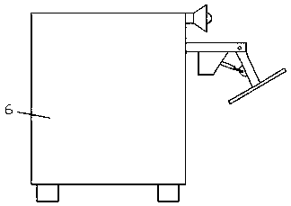
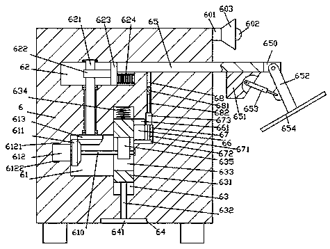
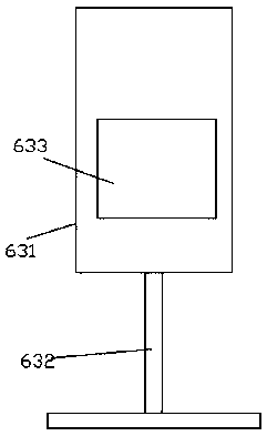
[0016] Such as Figure 1-Figure 4 As shown, a pole knocking device of the present invention includes a knocking base 6, a slot 64 is provided in the bottom surface of the knocking base 6, and a knocking plate 641 is smoothly fitted in the slot 64, and the knocking plate 641 is smoothly fitted in the slot 64. A first sliding cavity 63 is provided in the knockout base 6 above the slot 64, and a first sliding block 631 is smoothly fitted in the first sliding cavity 63, and a left and right through hole is arranged in the first sliding block 631. The fourth chute 633 is provided. The left inner wall of the first sliding chamber 63 communicates with a precursor chamber 61 elongated to the left. Rotating rod 610, the left extension end of the first rotating rod 610 is connected with the first power machine 612, the outer surface of the first power machine 612 is set in the inner wall of the left side of the front drive chamber 61 and is fixedly connected. The right extension sectio...


PUM


Abstract

The invention discloses a stable communication network connecting device which comprises a compacting base; a slot is formed in the bottom surface of the compacting base; a compacting plate is smoothly matched in the slot; a first sliding cavity is formed in the part, above the slot, of the compacting base; a first sliding block is smoothly matched in the first sliding cavity; a fourth sliding groove formed in a left and right penetrating manner is formed in the first sliding block; a precursor cavity extending leftwards is formed in the inner wall of the left side of the first sliding cavityin a communicating manner; the interior of the precursor cavity is rotationally matched and connected with a first rotary rod extending leftwards and rightwards; the left side extension tip of the first rotary rod is matched and connected with a first power machine; the outer surface of the first power machine is arranged in the inner wall of the left side of the precursor cavity and is fixedly matched and connected with the inner wall of the left side of the precursor cavity; the right side extension section of the first rotary rod stretches into the fourth sliding groove and the right side elongation tip of the first rotary rod is rotationally matched and connected with the inner wall of the right side of the first sliding cavity; and a first deflection wheel is fixedly arranged on the part of the outer surface, in the fourth sliding groove, of the first rotary rod. Automatic control on compacting work is realized, the pole fixing stability is improved, and the stability during movement or transportation is improved.

Description

technical field [0001] The invention relates to the technical field of knocking equipment, in particular to an electric pole knocking device. Background technique [0002] Every year in our country, a large number of wires and cables need to be newly erected to speed up the connection of the communication network. In order to avoid the damage of the power lines by strong wind loads, the stability of the poles needs to be increased in areas with soft soil. After backfilling the soil layer, use a shovel to tap it firmly on the surface. This method is time-consuming and laborious, and the soil density is low. In case of heavy rain, the soil foundation is easy to settle, and it is easy to cause the pole to fall. Especially in order to strengthen the fixing effect, the surface soil layer needs to be In the case of piles in a slope shape, it is difficult to make the soil density consistent by manual compaction. Contents of the invention [0003] The technical problem to be solv...

Claims


Application Information

Patent Timeline
Patent Type & Authority Patents(China)
IPC IPC(8): E02D3/074E04H12/34
CPCE02D3/074E04H12/34
Inventor 周军美
Owner 吴江市民福电缆附件厂
Why Eureka
Try Eureka