Tubular upper intake air type air curtain machine

A technology of upward air intake and air curtain machine, which is applied in the direction of mechanical equipment, non-variable pumps, machines/engines, etc., and can solve problems such as only horizontal air intake

Pending Publication Date: 2018-02-23
FOSHAN NANHAI NANYANG ELECTRIC APPLIANCE & MOTOR CO LTD
View PDF1 Cites 0 Cited by
  • Summary
  • Abstract
  • Description
  • Claims
  • Application Information

AI Technical Summary

Problems solved by technology

The wind rotor of this structure rotates forward, and the air duc

Method used


Image

  • Tubular upper intake air type air curtain machine
  • Tubular upper intake air type air curtain machine
  • Tubular upper intake air type air curtain machine

Examples


Embodiment Construction

[0019] The present invention will be further described below in conjunction with the accompanying drawings and embodiments.

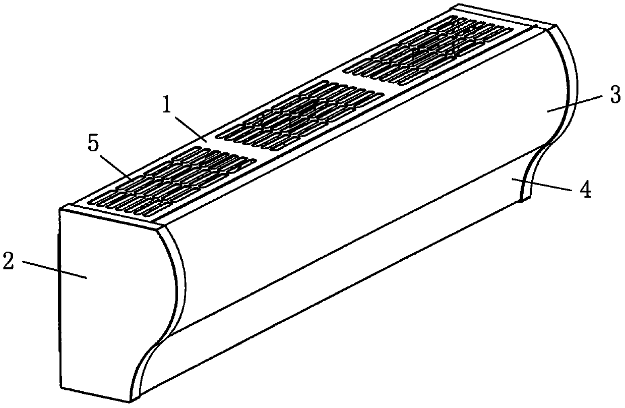
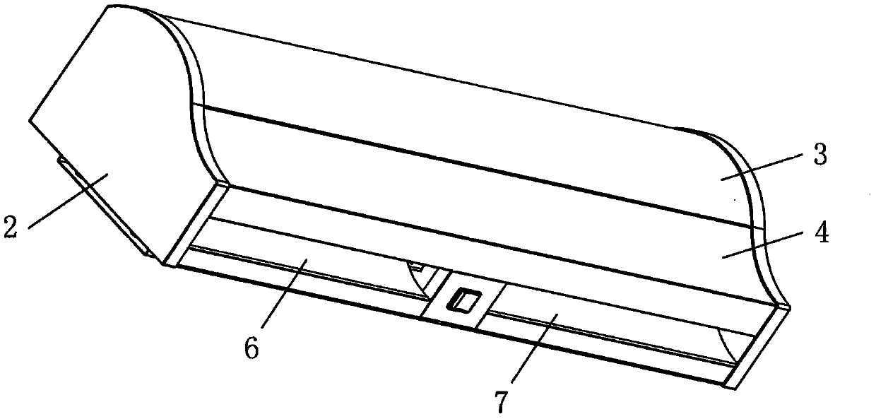
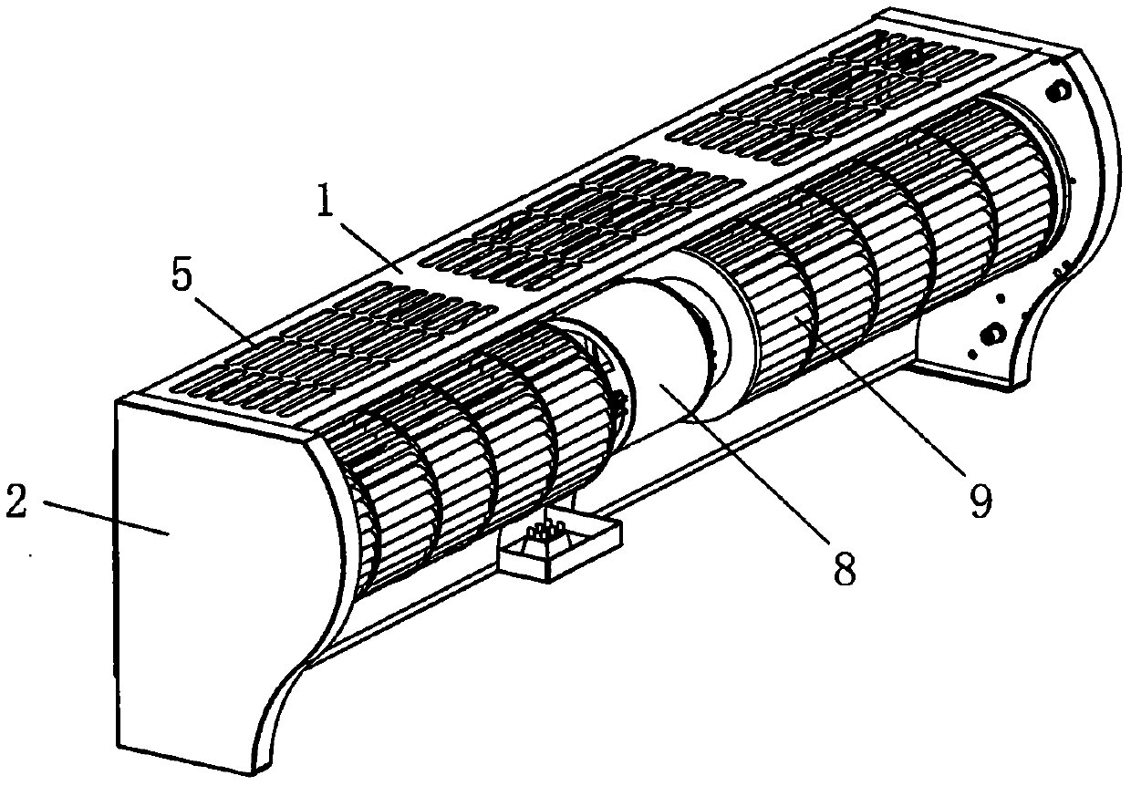
[0020] see Figure 1-Figure 6 , the cross-flow upward wind-intake air curtain machine, including a casing, and a motor 8 and an impeller 9 arranged in the inner cavity of the casing, the top and bottom of the casing are respectively provided with an air inlet 5 and an air outlet connected to the inner cavity 6. The casing includes a panel with a wavy inner wall, and the wind generated by the impeller 9 is blown along the wavy inner wall of the panel. The motor 8 of this structure drives the impeller to rotate in the opposite direction (clockwise), and then utilizes the wave-shaped inner wall on the panel as an air channel to supply air to realize the effect of upward air intake.

[0021] Further, the panel is formed by connecting the upper panel 3 and the lower panel 4 up and down, the upper panel 3 is provided with an arc-shaped inner wall with a sect...


PUM


Abstract

The invention relates to a cross-flow upward air-intake air curtain machine, which includes a casing, a motor and an impeller arranged in the inner cavity of the casing, and the top and bottom of the casing are respectively provided with an air inlet and an air outlet connected to the inner cavity ; The casing includes a panel with a wave-shaped inner wall, and the wind generated by the operation of the impeller is sent along the wave-shaped inner wall of the panel. By setting the motor to drive the impeller to rotate in the opposite direction, and using the wave-shaped inner wall on the panel as the air duct for air supply, the upward air intake effect of the air curtain machine is realized. It has the characteristics of simple design, reasonable structure, and air intake from above.

Description

technical field [0001] The invention relates to an air curtain machine, in particular to a through-flow upward air curtain machine. Background technique [0002] Chinese Patent Document No. CN101105184A disclosed a cross-flow air curtain machine on January 26, 2008, specifically disclosing a housing, housing end covers are installed at both ends of the housing, and a double-rotor motor is fixedly installed in the middle of the housing. Both sides of the dual-rotor motor are respectively driven and connected to the wind wheel. The wind wheel includes a wind wheel frame and blades. One end of the wind wheel frame is connected to the dual-rotor motor, and the other end is relatively rotatably installed inside the end cover of the shell. The longitudinal section of the shell It is in the shape of a whistle with the whistle downwards, and the whistle is an air outlet. An air inlet is provided on the side wall at the front and bottom of the housing, and an extended arc-shaped air...

Claims


Application Information

Patent Timeline
IPC IPC(8): F04D25/08F04D29/42F04D29/44
CPCF04D25/08F04D29/4226F04D29/441
Inventor 陆锡佳王成合
Owner FOSHAN NANHAI NANYANG ELECTRIC APPLIANCE & MOTOR CO LTD
Why Eureka
Try Eureka