Calibration burning method and device for camera

A programming method and camera technology, applied in the field of photography, can solve problems such as affecting the calibration accuracy, poor uniformity of calibration light brightness, and inability to calibrate and programming with a wide-angle camera module, so as to ensure brightness uniformity and improve accuracy. Effect

Active Publication Date: 2018-02-23
TRULY OPTO ELECTRONICS
View PDF3 Cites 3 Cited by
  • Summary
  • Abstract
  • Description
  • Claims
  • Application Information

AI Technical Summary

Problems solved by technology

[0004] In the prior art, a light source panel with a flat light-emitting surface is generally used to provide calibration light for the calibration and burning of the camera, which has the following disadvantages: 1. The distance from the edge of the light source panel to the camera is larger than the distance from the center to the camera. The brightness uniformity of the light is not good, which affects the calibration accuracy; 2. The viewing angle range that the light source panel can cover is only 120°, which cannot be used for calibration and burning of wide-angle camera modules; 3. With the development of mobile phone camera technology, multi-camera modules Grouping is a general trend. In order to obtain specific functions, multiple cameras with different field of view need to be integrated and used together. All cameras in this multi-camera module with multiple field of view need to be calibrated and burned under the same calibration light source. , which requires the calibration light source to be suitable for cameras with different field of view. For a multi-camera module with a wide-angle camera, the light source panel cannot fulfill this requirement

Method used


Image

  • Calibration burning method and device for camera
  • Calibration burning method and device for camera

Examples


Embodiment 1

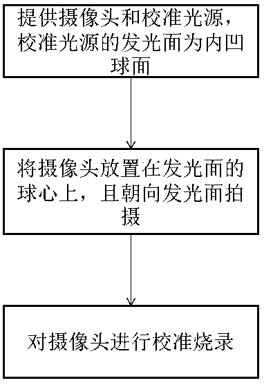
[0029] like figure 1 and 2 As shown, a calibration burning method of camera 2 includes:

[0030] Step 1: Provide a camera 2 and a calibration light source 1, the calibration light source 1 has a light-emitting surface 2, and the light-emitting surface 2 is a concave spherical surface;

[0031] Step 2: placing the camera 2 on the center of the sphere of the light-emitting surface 2, and shooting towards the light-emitting surface 2, the light-emitting surface 2 at least covers the viewing angle range of the camera 2;

[0032] Step 3: Calibrate and burn camera 2.

[0033] The calibration burning method adopts a calibration light source 1 whose light-emitting surface 2 is a concave spherical surface to calibrate and burn the camera 2. The distances from each point on the light-emitting surface 2 to the camera 2 are the same, which can maximize the Ensure the brightness uniformity of the calibration light to reduce the error of the calibration parameters caused by the brightnes...

Embodiment 2

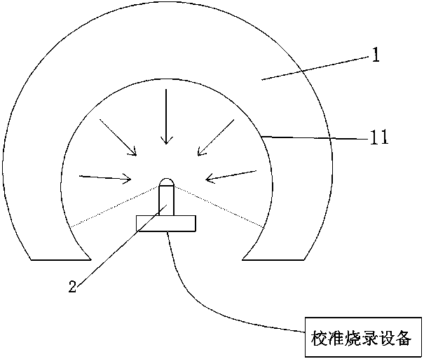
[0039] like figure 2 As shown, a calibration burning device for camera 2 includes:

[0040] The calibration light source 1 is used to provide the camera 2 with the calibration light required for calibration and burning, which has a light-emitting surface 2, and the light-emitting surface 2 is a concave spherical surface;

[0041] The bracket is used to support and fix the camera 2, so that the camera 2 is located on the center of the sphere of the light-emitting surface 2;

[0042] Calibration and burning equipment, used to control the camera 2 to perform calibration and burning in the calibration light source 1;

[0043] Wherein, the calibration burning device is electrically connected to the camera module.

[0044] The color temperature and / or illuminance of the calibration light source 1 can be adjusted. In actual implementation, LEDs with different color temperatures can be evenly distributed on the light-emitting surface 2, and the color temperature of the calibration ...


PUM


Abstract

The invention discloses a calibration burning method for a camera. The method comprises the following steps of step 1.providing the camera and a calibration light source, wherein the calibration lightsource is provided with a light emitting surface, and the light emitting surface is a concave spherical surface; step 2.placing the camera on the center of sphere of the light emitting surface and shooting towards the light emitting surface, wherein the light emitting surface at least covers the visual angle range of the camera; and step 3.carrying out calibration burning on the camera. Accordingto the calibration burning method, when the calibration burning is carried out on the camera, the error of calibration parameters can be reduced to be helpful for improving the accuracy of calibration burning of the camera. The invention further discloses a calibration burning device for the camera.

Description

technical field [0001] The invention relates to the field of photography, in particular to a method and device for calibrating and burning a camera. Background technique [0002] With the rapid development of mobile phone cameras, clients have higher and higher requirements for the imaging effect of the camera. However, due to individual differences, the imaging effects of each camera are not the same, and it is difficult to achieve consistent imaging effects for all cameras only with a set of fixed imaging parameters. [0003] In order to improve the consistency of the imaging effect of the camera, the camera is usually calibrated and burned before leaving the factory. When the client uses the camera, it only needs to read the calibration parameters pre-burned in the camera and apply it to the captured image. It is possible to achieve consistent imaging effects among the cameras. [0004] In the prior art, a light source panel with a flat light-emitting surface is general...

Claims


Application Information

Patent Timeline
Patent Type & Authority Applications(China)
IPC IPC(8): H04N17/00
CPCH04N17/002
Inventor 廖师儒张博李建华
Owner TRULY OPTO ELECTRONICS
Why Eureka
Try Eureka