
Control channel transmission indication method, detection method, base station and user equipment

A technology of control channel and indication information, which is applied in the field of base station and user equipment, detection method, control channel transmission indication, and can solve the problems of high power consumption and high implementation complexity of UE

Active Publication Date: 2018-02-23
CHINA MOBILE COMM LTD RES INST +1
View PDF3 Cites 7 Cited by
  • Summary
  • Abstract
  • Description
  • Claims
  • Application Information

AI Technical Summary

Problems solved by technology

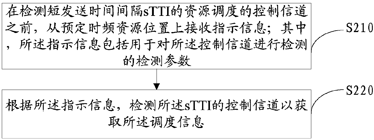
When a UE that supports sTTI transmission wants to obtain the scheduling information of each sTTI in real time, it needs to detect the sPDCCH control channel of the sTTI. However, if the existing number of blind detections in each sTTI is still maintained, on the one hand, the implementation complexity of the UE is high. On the other hand, the power consumption of the UE is also relatively large

Method used


Image

  • Control channel transmission indication method, detection method, base station and user equipment
  • Control channel transmission indication method, detection method, base station and user equipment
  • Control channel transmission indication method, detection method, base station and user equipment

Examples


example 1

[0149] This example abandons the current practice of defining a search space for each UE. That is, the control channel area is determined according to the actual control channel overhead, and the control channel area is indicated to the UE in an explicit or implicit manner, and all user equipment UEs detect their own control channels in the same control channel area. The following specifically provides three implementation schemes:

[0150] Option One:

[0151] By using sTTI-specific information in the sTTI to indicate (the sTTI-specific information corresponds to the aforementioned indication information) the following information:

[0152] The number of constituent units (for example, the number of sCCEs) contained in the control channel in the current sTTI is equivalent to the ability to determine the size of the control channel region.

[0153] All UEs perform blind detection of control channels according to different aggregation levels in the control channel area of ​​t...

example 2

[0167] Such as Figure 7 As shown, this example provides an information processing method, including:

[0168] Step S1: the base station performs resource scheduling, and generates scheduling information according to the result of resource scheduling;

[0169] Step S2: the base station generates indication information according to the transmission parameters of the control channel carrying the scheduling information;

[0170] Step S3: the base station sends indication information and scheduling information in sequence.

[0171] Step S4: the user equipment receives indication information and scheduling information;

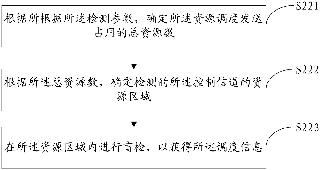
[0172] Step S5: The user equipment at least determines the total number of resources of the control channel occupied by the control channel according to the indication information, and determines the resource area occupied by the control channel according to the total number of resources;

[0173] Step S6: The user equipment performs blind detection of schedulin...


PUM


Abstract

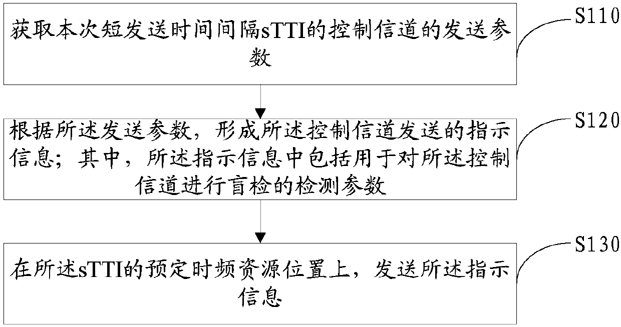
The embodiment of the invention discloses a control channel transmission indication, a detection method, a base station and user equipment. The control channel transmission indication method comprisesthe steps of acquiring a sending parameter of a control channel of a current short transmission time interval sTTI; forming indication information sent by the control channel according to the sendingparameter, wherein the indication information comprises a detection parameter used for performing detecting the control channel; and sending the indication information on a predetermined time frequency resource position of the sTTI. Therefore, the base station not only can send scheduling information via the control channel, but also can send the indication information; the user equipment can acquire the indication information before detecting scheduling information of the control channel; the indication information is determined according to the sending parameter of the control channel, so that the hesitancy degree of blind detection of the user equipment can be reduced, and thus the complexity of blind detection is reduced, the blind detection efficiency of the control channel can be enhanced, and the power consumption of blind detection is reduced.

Description

technical field [0001] The invention relates to the field of wireless communication, in particular to a control channel transmission instruction, a detection method, a base station and user equipment. Background technique [0002] In a Long Term Evolution (LTE) system, it is necessary to send scheduling information to a user equipment (User Equipment, UE) through a physical downlink control channel (Physical Downlink Control Channel, PDCCH); in this way, the UE can determine the The physical shared channel, transmission format, and power information that can be used to transmit information by itself, so as to correctly decode and send and receive data. The UE needs to obtain the scheduling information through blind detection. In the prior art, in order to reduce the number of busy detections of the UE, it will be set in the dedicated search space of the PDCCH; the time-frequency resource corresponding to the dedicated search space is less than the entire The time-frequency ...

Claims


Application Information

Patent Timeline
IPC IPC(8): H04W72/04H04W72/14H04L1/00
CPCH04L1/0038H04W72/23Y02D30/70
Inventor 胡丽洁侯雪颖
Owner CHINA MOBILE COMM LTD RES INST
Learn More