Centrifugal grain breaking machine

A particle breaker and centrifugal technology, which is applied in the field of machinery, can solve the problems of continuous adhesion and poor particle breaking effect, and achieve the effects of not easy adhesion, simplified structure and reasonable design.

Inactive Publication Date: 2018-02-27
丁章云
View PDF9 Cites 0 Cited by
  • Summary
  • Abstract
  • Description
  • Claims
  • Application Information

AI Technical Summary

Problems solved by technology

[0002] With the development of modern mechanical processing, a variety of breaking machines have emerged on the market continuously and with each passing day. However, the breaking machines that appear on the market often have poor breaking effects or continuous adhesion. Now it is urgent Need a kind of grain breaker with good breaking effect and economical applicability

Method used


Image

  • Centrifugal grain breaking machine
  • Centrifugal grain breaking machine

Examples


Embodiment Construction

[0017] The present invention will be further described below in combination with specific embodiments.

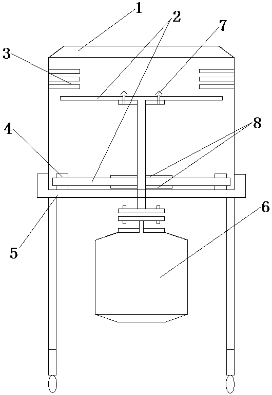
[0018] Such as figure 1 As shown, a centrifugal grain breaker mainly includes a grain breaker and an external motor 6, the grain breaker is fixed above the motor 6 through a bracket 5, and the motor 6 is connected with the grain breaker through a centrifugal rod. The top of the breaker box is a hopper 1, and the inside of the breaker box includes a centrifugal disc 2, a grid booster rod 3, a discharge port 4 and a fixing bolt 7, and the centrifugal disc 2 is respectively fixed on the top and bottom of the centrifugal rod. The centrifugal disc 2 and the centrifugal rod are fixed by fixing bolts 7, and the barrier booster rod 3 is respectively located above the two ends of the centrifugal disc 2, the barrier booster rod 3 is higher than the centrifugal disc 2, and the bottom end of the bracket 5 has ten thousand to the wheel.

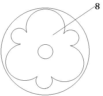
[0019] The upper and lower surfaces of the cen...


PUM


Abstract

The invention discloses a centrifugal grain breaking machine. The centrifugal grain breaking machine mainly comprises a grain breaking box and an external motor, wherein the grain breaking box is fixedly arranged above the motor through a support; the motor is connected with the grain breaking box through a centrifugal rod; a hopper is arranged at the top of the grain breaking box; the interior ofthe grain breaking box comprises centrifugal pans, blocking gate power assisting rods, a discharge hole and a fixed bolt; the centrifugal pans are fixed to the top end and the bottom end of the centrifugal rod respectively; the centrifugal pans are fixed with the centrifugal rod through the fixed bolt; the blocking gate power assisting rods are positioned above two ends of the centrifugal pans respectively; the blocking gate power assisting rods are higher than the centrifugal pans; and universal wheels are arranged at the bottom end of the support. According to the centrifugal grain breakingmachine disclosed by the invention, grain breaking is carried out through the centrifugal force of the motor, and the centrifugal grain breaking machine is good in effect and is further unlikely to adhere; and the centrifugal grain breaking machine is simple in structure and reasonable in design, and is widely applied to production and processing industries.

Description

technical field [0001] The invention relates to the technical field of machinery, and more specifically relates to a centrifugal grain breaker. Background technique [0002] With the development of modern mechanical processing, a variety of breaking machines have emerged on the market continuously and with each passing day. However, the breaking machines that appear on the market often have poor breaking effects or continuous adhesion. Now it is urgent A grain breaking machine with good grain breaking effect and economical applicability is needed. Contents of the invention [0003] Purpose of the invention: The purpose of the present invention is to provide a centrifugal grain breaker for the deficiencies and defects of the prior art. The grain breaker made according to the technical solution provided by the present invention has a good grain breaker effect. [0004] Technical solution: In order to achieve the above purpose, the technical solution adopted in the present i...

Claims


Application Information

Patent Timeline
Patent Type & Authority Applications(China)
IPC IPC(8): B01J2/14
CPCB01J2/14
Inventor 丁章云
Owner 丁章云
Why Eureka
Try Eureka