
Mounting base capable of sliding

A technology of mounting seat and tie rod, which is applied in the direction of instruments, electrical digital data processing, and digital data processing components, etc., which can solve the problems of easy disconnection and large connection distance of connected equipment, and achieves avoiding disconnection, convenient placement, and fast wiring Effect

Inactive Publication Date: 2018-02-27
MIANYANG XINYANG INTPROP CO LTD
View PDF6 Cites 0 Cited by
  • Summary
  • Abstract
  • Description
  • Claims
  • Application Information

AI Technical Summary

Problems solved by technology

The adapter also needs to be managed by the mounting base during use, and multiple adapters are placed on one mounting base. Due to the position of the existing mounting base, it can only be moved as a whole, resulting in the connection distance between some adapters placed on the mounting base and the connected equipment. large, leading to easy dropouts

Method used


Image

  • Mounting base capable of sliding

Examples


Embodiment 1

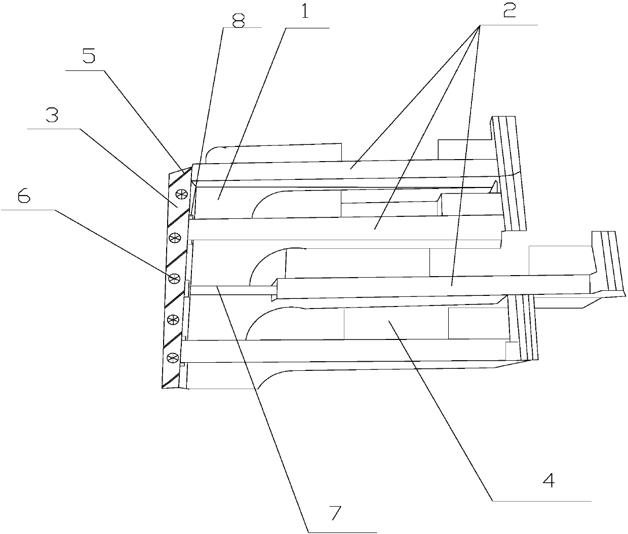
[0021] Such as figure 1 As shown, the present invention includes a slidable mounting base, including a plurality of isolation baffles 1, a plurality of pull rods 7, a base plate 3 and a chuck 8, and the pull rods 7 and the isolation baffles 1 are successively installed at intervals on the front of the base plate 3. A plurality of fans 6 and heat dissipation seams 5 are sequentially installed on the back side of the substrate 3; wire release holes 4 are also set between adjacent pull rods 7 and isolation baffles 1; push-pull plates 2 are set on each pull rod 7, The push-pull plate 2 can move back and forth on the pull rods 7 , and a chuck 8 for limiting the movement of the push-pull plate 2 is also provided at the fixed end of each pull rod 7 .

[0022] When in use, the adapter is placed on the corresponding push-pull board for work, and a special isolation baffle is set between the two push-pull boards to isolate the signals between different adapters to avoid mutual influence...

Embodiment 2

[0024] This embodiment is preferably as follows on the basis of Embodiment 1: a moisture-proof base is also provided at the bottom of the push-pull plate 2 . If the mounting base is placed directly underground, the damp air at the bottom will easily corrode the push-pull plate, resulting in damage to the mounting base. However, this solution sets a moisture-proof base to distance the push-pull plate from the ground to avoid corrosion by humid air and prolong the service life. .

[0025] A handle is also provided at one end of the push-pull plate 2, and threads are provided on the handle. Improve grip comfort.

[0026] The chuck 8 and the push-pull plate 2 are locked or opened and closed in a rotating manner. It is convenient and simple to lock or open and close in this way.

[0027] The width of the isolation baffle 1 fixed at the end of the base plate 3 is the same as the distance between two adjacent tie rods 7 . In order to achieve better isolation effect.

[0028] The...


PUM


Abstract

The invention discloses a mounting base capable of sliding. The mounting base comprises multiple separation baffles, multiple pull rods, a base plate and clamping heads. The pull rods and the separation baffles are sequentially mounted on the front surface of the base plate at intervals, multiple heat dissipation fans are mounted on the back surface of the base plate in sequence, and heat dissipation seams are formed in the back surface of the base plate in sequence; pay-off holes are further formed between the adjacent pull rods and separation baffles; a push-pull plate sleeves each pull rod,the push-pull plates can move front and back on the pull rods, and the clamping heads used for limiting movement of the push-pull plates are further arranged at the fixed ends of all the pull rods. Through the structure, the position of each adapter which is mounted on the mounting base can be locally adjusted so that suitable distances can be kept between all the placed adapters and a connectiondevice, and wire dropping is avoided.

Description

technical field [0001] The invention relates to the communication field, in particular to a slidable mounting base. Background technique [0002] Adapter is the Chinese translation of English Adapter / adaptor. An adapter is an interface converter, which can be an independent hardware interface device that allows a hardware or electronic interface to be connected to another hardware or electronic interface, or it can be an information interface. The wireless adapter is usually referred to as the wireless network card. The function of the wireless network card is similar to that of the network card in the Ethernet. It is used as the interface of the wireless local area network to realize the connection with the wireless local area network. Wireless network cards are mainly divided into three types according to different interface types, namely PCMCIA wireless network cards, PCI wireless network cards and USB wireless network cards. PCMCIA wireless network card is only suitabl...

Claims


Application Information

Patent Timeline
IPC IPC(8): G06F1/18
CPCG06F1/185
Inventor 龚平
Owner MIANYANG XINYANG INTPROP CO LTD
Learn More