Combined centering type blade mounting angle measurement device

An angle measurement device and blade installation technology, which is applied in angle/taper measurement and other directions, can solve the problems of lack of precise positioning of the measurement device, insufficient accuracy of measurement results, and insufficient rigidity of rods, etc., to achieve simple structure, easy control of precision, and data precise effect

Active Publication Date: 2018-03-02
HANGZHOU STEAM TURBINE
View PDF8 Cites 7 Cited by
  • Summary
  • Abstract
  • Description
  • Claims
  • Application Information

AI Technical Summary

Problems solved by technology

Since the fixed structure of the blade and the inner and outer edges cannot be directly measured with an angle gauge, the conventional method is to draw a line at a certain height section of the blade, then use a flat plate to assist the end face positioning, and then measure with an angle gauge. There is no positioning on the flat plate. This measurement method has low accuracy and low repeatability, and it is impossible to perform a large number of accurate measurements.
And disclosed this kind of device is also very limited, as the patent publication number is CN102788547A, the measuring device of a disclosed a kind of axial flow fan blade installation angle, comprises connecting rod, is respectively vertically installed with reference rod and measuring length at the two ends of connecting rod rod, and the long measuring rod is perpendicular to the plane formed by the reference rod and the connecting rod, a pointer is vertically fixed at one end of the long measuring rod, and the pointer and the reference rod are perpendicular to each other, and a dial is vertically installed at one end of the long measuring rod, The dial is close to the pointer and can rotate left and right around the installation point. The bottom edge of the dial is flat, and the scale value is marked on the dial
This device has the defect of insufficient rigidity of the rod, and also lacks the precise positioning of the measuring device, resulting in insufficient accuracy of the measurement results

Method used


Image

  • Combined centering type blade mounting angle measurement device
  • Combined centering type blade mounting angle measurement device
  • Combined centering type blade mounting angle measurement device

Examples


Embodiment Construction

[0022] The technical solutions of the present invention will be further specifically described below through the embodiments and in conjunction with the accompanying drawings.

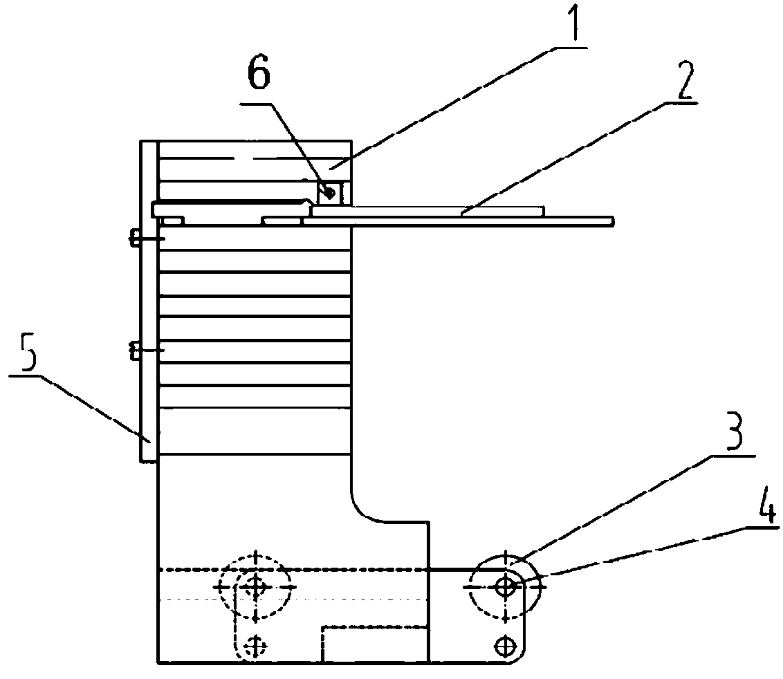
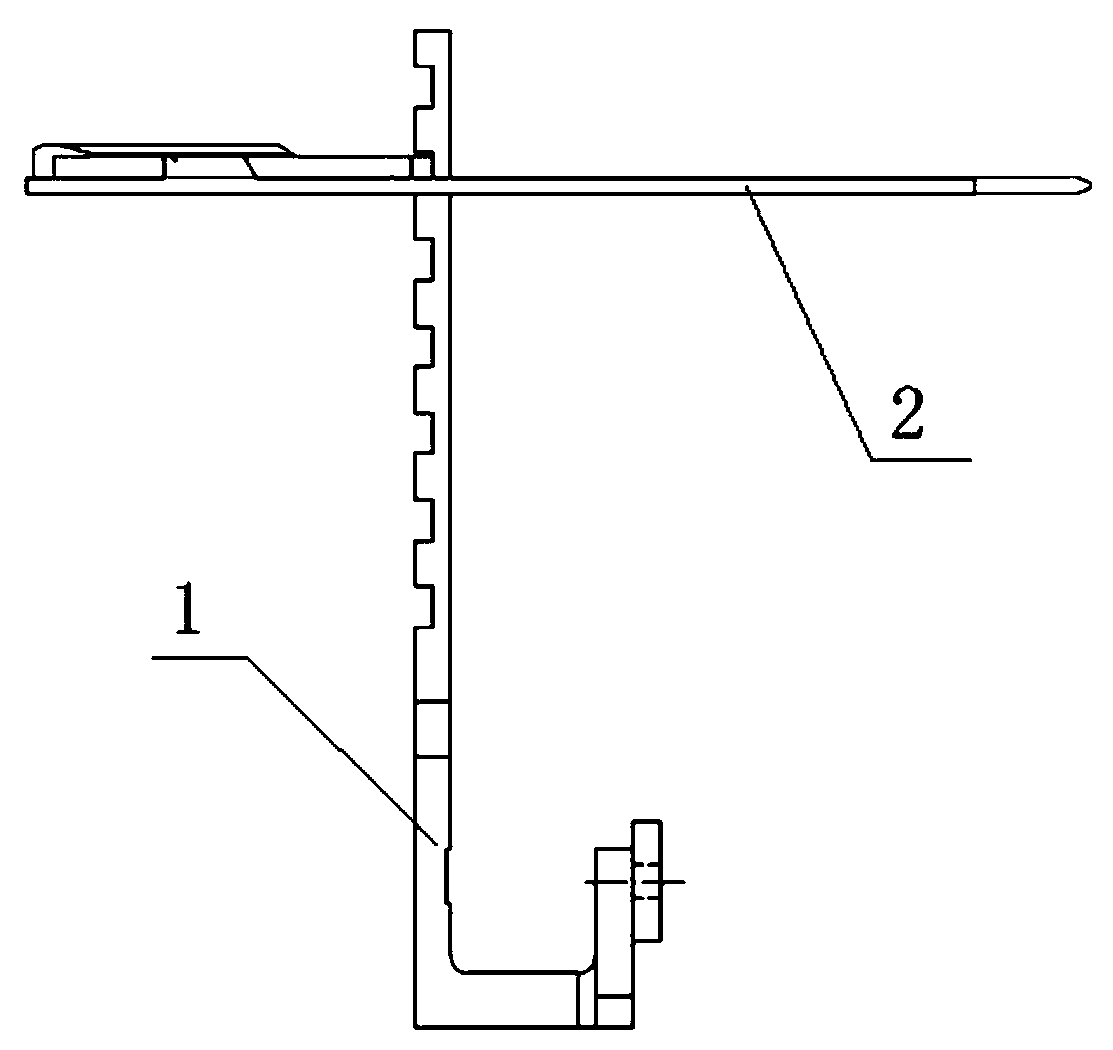
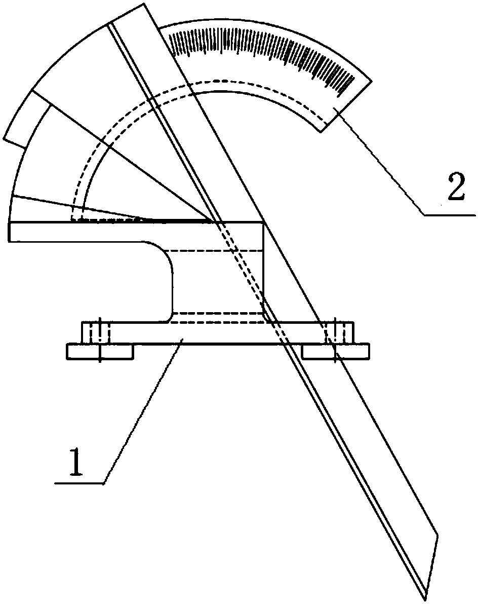
[0023] This embodiment is a combined centering type blade installation angle measuring device. Its working principle is: set a group of support rollers 3 for supporting and positioning the inner ring or outer ring of the measured blade 7, so that the measured blade 7 has automatic positioning. Cardiac Function. Then arrange the angle gauge 2 on the corresponding part of the tested blade 7, so that the rotation center of the angle gauge 2 passes through the radial centerline of the inner ring or outer ring of the tested blade 7 vertically, and at the same time, the measuring section of the tested blade can be accurately positioned. During measurement, the blade under test 7 is slid along the supporting arc surface formed by the support roller 3, and the relative position of the angle gauge 2 and the bla...


PUM


Abstract

The invention discloses a combined centering type blade mounting angle measurement device. The combined centering type blade mounting angle measurement device is characterized in that a set of supporting rollers used for supporting and positioning an inner ring and an outer ring of a detected blade are set, and the detected blade is made to have the automatic centering function; an angle gauge isarranged at the corresponding portion of the detected blade, a rotation center of the angle gauge is made to be perpendicular to a radiation center line of the inner ring or the outer ring of the detected blade, and the measurement cross section of the detected blade can be accurately positioned; during measurement, the detected blade is made to slide along a supporting cambered surface through supporting the supporting cambered surface formed by the supporting rollers, the relative position of the angle gauge and the detected blade and a measurement arm of the angle gauge are adjusted, so themeasurement arm of the angle gauge and an inner arc of the blade are made to completely fit at a certain relative position, and a mounting angle of the detected blade is acquired. The combined centering type blade mounting angle measurement device is advantaged in that the detected blade in a sliding state is stable and reliable, measured data is accurate, the structure is simple, device precision is easy to control, operation is simple, assembling is convenient, and detection efficiency is high.

Description

technical field [0001] The invention relates to the detection technology of steam turbine components, in particular to a combined centering blade installation angle measuring device. Background technique [0002] In fluid machinery products, especially in stationary vane rings, the vanes are combined with the inner and outer bands. Before and after the combination, the installation angle of a certain height of the vanes must be measured, inspected and adjusted. Since the fixed structure of the blade and the inner and outer edges cannot be directly measured with an angle gauge, the conventional method is to draw a line at a certain height section of the blade, then use a flat plate to assist the end face positioning, and then measure with an angle gauge. There is no positioning on the plate, and this measurement method has low accuracy and low repeatability, and it is impossible to perform a large number of accurate measurements. And disclosed this kind of device is also ver...

Claims


Application Information

Patent Timeline
Patent Type & Authority Applications(China)
IPC IPC(8): G01B5/24
CPCG01B5/24
Inventor 陈金铨王皋隋永枫徐志明方寅邵艳红郑健生祝华云但汉攀张春梅王宏泽沈金高刘红燕
Owner HANGZHOU STEAM TURBINE
Why Eureka
Try Eureka