An injection mold with adjustable glue feed

A technology of injection mold and glue feeding amount, which is applied in the field of injection molding molds, can solve the problems of quality, processing efficiency, single adjustment of glue feeding amount, pressure and glue feeding amount inconsistency, and achieve the effect of quality assurance

Inactive Publication Date: 2019-11-08
SHENZHEN XIAOFENGLI PLASTIC HARDWARE
View PDF1 Cites 0 Cited by
  • Summary
  • Abstract
  • Description
  • Claims
  • Application Information

AI Technical Summary

Problems solved by technology

[0002] At present, for the injection molds of large plastic products, the gating system of the injection molds often adopts multi-point glue feeding, so as to achieve simultaneous glue feeding everywhere and improve the injection molding efficiency. The runners generally take the main channel to each inlet The shortest distance between the glue points can save materials, but due to the multi-point glue injection, this will make the speed of each glue point inconsistent, which will lead to inconsistent pressure and glue injection in the cavity, which often leads to problems in the injection molding process. The lack of material, burnt and other poor appearance of the product and the ejection problem caused by the excessive tightness of the product due to partial overfilling, so the injection speed (that is, the amount of glue) has a great influence on the quality of the product and the efficiency of processing. However, on the current injection mold, the single adjustment of the amount of glue

Method used


Image

  • An injection mold with adjustable glue feed
  • An injection mold with adjustable glue feed

Examples


Embodiment Construction

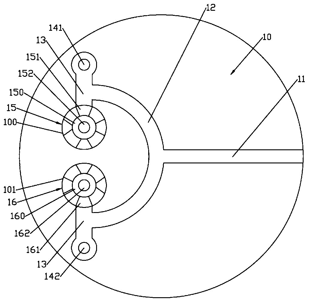
[0013] Such as figure 1 As shown, an injection mold with adjustable glue feed includes a mold body 10; the surface of the mold body 10 is formed with a main channel 11 arranged left and right; the left end of the main channel 11 is connected with a central arc-shaped flow channel 12; the center arc-shaped The front end and the rear end of the runner 12 are respectively connected with a runner 13; the front end of the runner 13 on the front side is connected with a first branch runner 141 communicating with the molding cavity of the mold body 10; the rear end of the runner 13 on the rear side is connected to There is a second branch channel 142 communicating with the molding cavity of the mold body 10; the left side of the surface of the mold body 10 is formed with a cylindrical groove-shaped front adjustment groove 100 and a rear adjustment groove 101; the front adjustment groove 100 and the rear adjustment groove 101 are front and rear Symmetrically arranged; the front adjust...


PUM


Abstract

The invention discloses an injection mold with adjustable glue inlet quantity. The injection mold with adjustable glue inlet quantity comprises a mold body; a main flow channel arranged left and rightis formed in the surface of the mold body; the main flow channel is communicated with a first branched flow channel, a second branched flow channel, a third branched flow channel and a fourth branched flow channel separately; a front central groove is formed in the upper end face of a front adjusting block arranged rotatably; an inlet of the third branched flow channel is formed in the bottom surface of the front central groove; a plurality of circumferentially distributed front feeding ports are formed in the side wall of the front central groove in an inner and outer run-through mode; the arc length of the outer side ends of the plurality of front feeding ports is equal, and the arc length of the inner side end of the plurality of front feeding ports is reduced clockwise; a back centralgroove is formed in the upper end face of a back adjusting block arranged rotatably; an inlet of the fourth branched flow channel is formed in the bottom surface of the back central groove; a plurality of circumferentially distributed back feeding ports are formed in the side wall of the back central groove in an inner and outer run-through mode; and the arc length of the outer side ends of the plurality of back feeding ports is equal, and the arc length of the inner side end of the plurality of back feeding ports is reduced clockwise. The injection mold with adjustable glue inlet quantity can effectively adjust the quantity of the glue injected into a forming cavity of the mold and guarantees the forming quality of products.

Description

technical field [0001] The invention relates to the technical field of injection molds, in particular to an injection mold with adjustable glue feed. Background technique [0002] At present, for the injection molds of large plastic products, the gating system of the injection molds often adopts multi-point glue feeding, so as to achieve simultaneous glue feeding everywhere and improve the injection molding efficiency. The runners generally take the main channel to each inlet The shortest distance between the glue points can save materials, but due to the multi-point glue injection, this will make the speed of each glue point inconsistent, which will lead to inconsistent pressure and glue injection in the cavity, which often leads to problems in the injection molding process. The lack of material, burnt and other poor appearance of the product and the ejection problem caused by the excessive tightness of the product due to partial overfilling, so the injection speed (that is...

Claims


Application Information

Patent Timeline
Patent Type & Authority Patents(China)
IPC IPC(8): B29C45/30B29C45/27
CPCB29C45/2725B29C45/30
Inventor 徐亚维
Owner SHENZHEN XIAOFENGLI PLASTIC HARDWARE
Why Eureka
Try Eureka