Positioning device and metal plate automatic production line

An automatic production line and positioning device technology, applied in positioning devices, feeding devices, storage devices, etc., can solve the problems of gear and rack wear of transmission parts, large deviation of discharging position, and scrapped workpieces, so as to ensure stamping quality, The effect of low cost and simple structure

Inactive Publication Date: 2018-03-09
GREE ELECTRIC APPLIANCES INC
View PDF5 Cites 3 Cited by
  • Summary
  • Abstract
  • Description
  • Claims
  • Application Information

AI Technical Summary

Problems solved by technology

When the processing workshop speeds up the production tempo of the automatic line in order to improve production efficiency, the inertia of the beam that drives the manipulator movement will also increase, resulting in a large deviation in the discharging position
At the same time, the automatic line works for a long time, and the gear and rack of the transmission parts of the automatic line will be worn to varying degrees. When the wear gap of the transmission parts of the automatic line is too large, there will be a large deviation in the position where the manipulator puts the workpiece into the mold. Multiple adjustments to automatic line molds
In addition, if the blanking size is too large or too small, the way the automatic line manipulator grabs the material will also affect the feeding position of the automatic line, resulting in the problem that the workpiece cannot be positioned close to the processing, which will cause the workpiece to be scrapped after stamping, affecting the production efficiency of the automatic line. Increased processing and production costs

Method used


Image

  • Positioning device and metal plate automatic production line
  • Positioning device and metal plate automatic production line
  • Positioning device and metal plate automatic production line

Examples


Embodiment 1

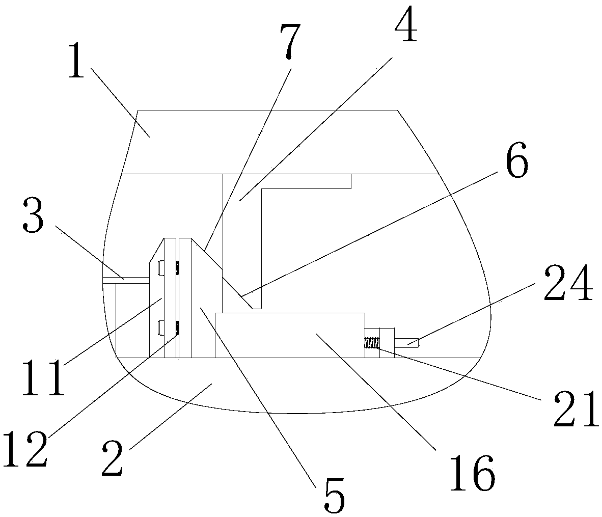
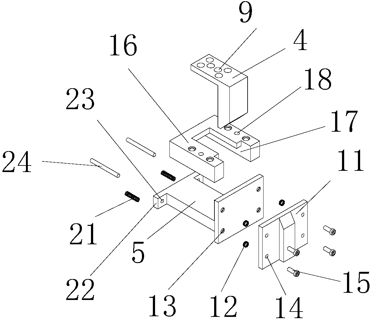
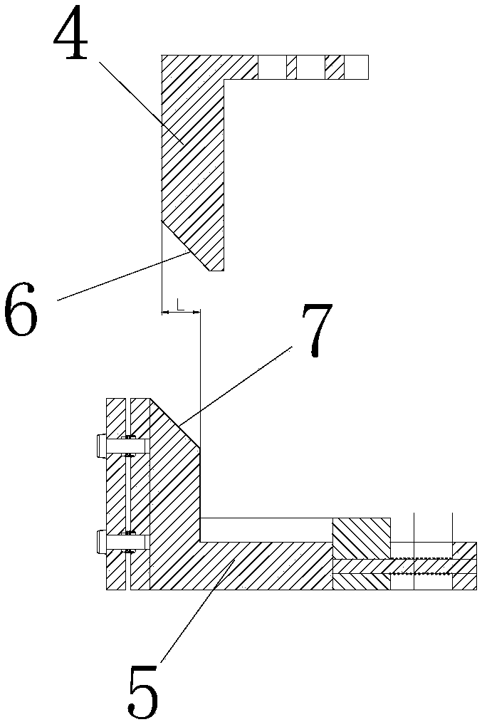
[0050] like figure 1 and figure 2 As shown, a positioning device is used on the mold of the production line. The mold of the production line includes: an upper mold 1 and a lower mold 2, and the upper mold 1 and the lower mold 2 work together to complete the stamping work of the workpiece 3 placed on the lower mold 2 , the positioning device includes: a drive block 4 and a slider 5. The drive block 4 is fixedly connected to the upper die 1, and the slide block 5 is movably connected to the lower die 2. The driving block 4 moves under the drive of the upper die 1, and drives the slider 5 to slide on the lower die 2, and the slider 5 pushes the workpiece 3 to move on the lower die 2 to adjust the position of the workpiece 3.

[0051] Wherein the driving effect of the driving block 4 on the slider 5 can be specifically as follows figure 1 As shown in , the driving block 4 has a driving slope 6, and the slider 5 has a receiving slope 7 corresponding to the driving slope 6.

...

Embodiment 2

[0071] An automatic sheet metal production line is provided with a mold on the automatic sheet metal production line, and the positioning device described in the first embodiment is provided on the mold.

[0072] Preferably, as Figure 7 As shown, a positioning block 25 is also included. As mentioned above, the mold includes an upper mold (not shown in the figure) and a lower mold 2 . The lower mold 2 has a rectangular sheet material holding area 26. In the work, the workpiece is placed in the sheet metal holding area. The workpiece mentioned here can be a sheet metal wool, and the upper mold and the lower mold 2 work together to carry out the sheet metal wool. Stamping shear work.

[0073] The two adjacent sides of the sheet material holding area are fixed sides 27 , and the other two sides are adjustment sides 28 . The number of positioning blocks 25 is at least two, and they are respectively arranged along the two fixed sides 27 , that is to say, at least one positioning ...


PUM


Abstract

The invention relates to a positioning device and a metal plate automatic production line. The positioning device is used for a production line die and the production line die includes an upper die and a lower die. The upper die and the lower die act jointly, to complete stamping on a workpiece on the lower die. The positioning device includes a driving block and a sliding block. The driving blockis fixedly connected with the upper die, the sliding block is movably connected to the lower die, the driving block is driven by the upper die to move and drives the sliding block to slide on the lower die, and the sliding block pushes the workpiece to move on the lower die, to adjust the position of the workpiece. The positioning device has the advantages of being reasonable in design, simple instructure and low in cost and capable of automatically correcting the workpiece on the lower die to make the position of the workpiece accurate and ensure metal plate stamping quality.

Description

technical field [0001] The invention relates to the technical field of mechanical manufacturing, in particular to a positioning device and an automatic sheet metal production line. Background technique [0002] In the current automatic processing of sheet metal stamping, it is necessary to accurately position the workpiece. Some workpieces require relatively high processing and positioning accuracy, and the general error is ±0.05mm. The production method adopts the manipulator to grab the material workpiece from the upper station mold or wool stack and put it into the lower station mold. Usually the lower station mold adopts the fixed positioning method of four-side positioning. When the manipulator grasps the workpiece from the upper station to the lower station, the manipulator brakes suddenly after high-speed movement. Due to inertia, the position of the manipulator for discharging materials often has deviations. When the processing workshop speeds up the production temp...

Claims


Application Information

Patent Timeline
Patent Type & Authority Applications(China)
IPC IPC(8): B21D43/00
CPCB21D43/003
Inventor 李毅陶志鹏
Owner GREE ELECTRIC APPLIANCES INC
Why Eureka
Try Eureka