Supercharge Your Innovation With Domain-Expert AI Agents!

A detachable mounting structure for sub-frame and vehicle body

A technology for mounting structure and sub-frame, which is applied to the substructure, vehicle components, transportation and packaging, etc., can solve the problems of endangering the personal safety of drivers and occupants, the collision energy is not absorbed in time, and the deformation energy absorption space is small. Achieve the effect of reducing intrusion, avoiding further damage, and increasing the deformation energy absorption space

Active Publication Date: 2019-10-18
SOUTH CHINA UNIV OF TECH
View PDF2 Cites 0 Cited by
  • Summary
  • Abstract
  • Description
  • Claims
  • Application Information

AI Technical Summary

Problems solved by technology

[0006] The present invention is mainly aimed at the frontal collision of the automobile, because the deformation and energy absorption space of the front part of the vehicle body is small, the collision energy is not absorbed in time, resulting in too much hard power assembly intruding into the passenger compartment, endangering the personal safety of the driver and passengers Problem, a mounting structure is proposed to realize the separation of the subframe and the body during the frontal collision of the car. The powertrain sinks under the action of its own gravity, which increases the deformation and energy absorption space of the longitudinal beam of the car body and improves the safety of the vehicle collision. performance, and compared with the existing technology, the processing and manufacturing are simple, and the separation effect of the sub-frame and the body is better

Method used


Image

  • A detachable mounting structure for sub-frame and vehicle body
  • A detachable mounting structure for sub-frame and vehicle body
  • A detachable mounting structure for sub-frame and vehicle body

Examples


Embodiment Construction

[0026] The technical solution of the present invention will be further specifically described below through an embodiment and in conjunction with the accompanying drawings.

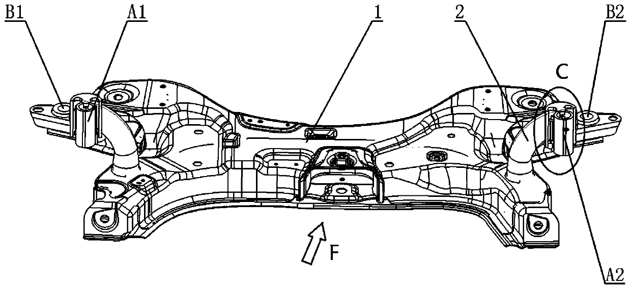
[0027] Such as figure 1 In the shown front subframe of the vehicle, the front subframe is connected to the vehicle body not shown in detail from below, and has four connection positions with the vehicle body, which are respectively connected to the corresponding positions of the vehicle body. Frame and body front connection points A1, A2 and two sub-frames and body rear connection points B1, B2. In this embodiment, the installation structure of this embodiment that can realize the detachment of the sub-frame from the vehicle body is used at the front connection points A1 and A2 of the front sub-frame. The mounting structure is welded at the horn 2 of the sub-frame body 1 .

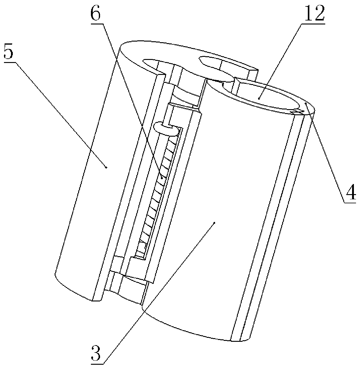
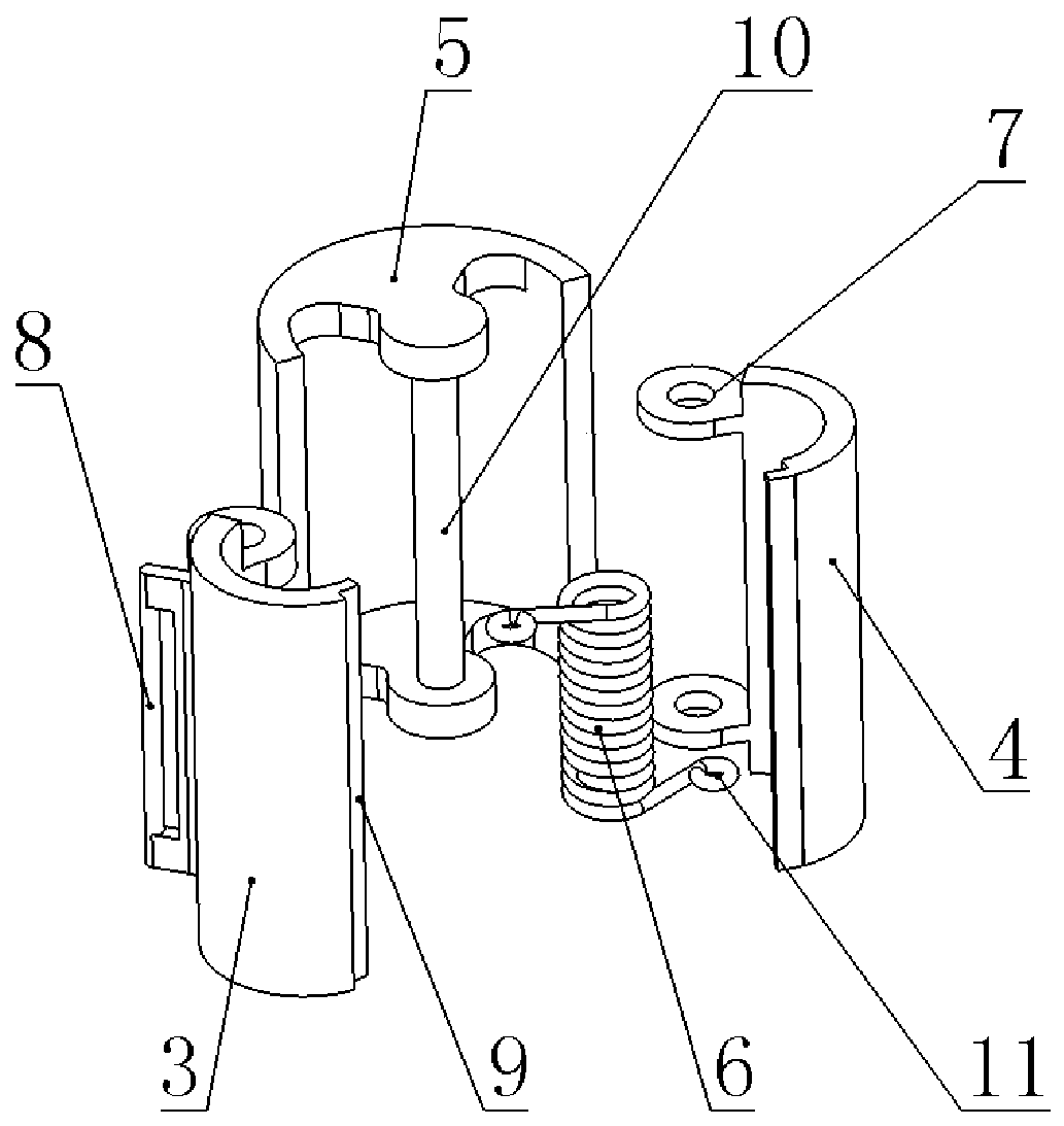
[0028] Such as figure 2 As shown, a detachable mounting structure for the subframe and the vehicle body includes an openable and...


PUM


Abstract

The invention discloses a mounting structure with an auxiliary frame capable of being detached from a vehicle body. The mounting structure comprises an openable sleeve device and a connecting bolt mechanism, wherein the openable sleeve device is fixed on an auxiliary frame body; the connecting bolt mechanism is positioned in a center hole of the openable sleeve device and is connected with a longitudinal girder of the vehicle body to enable the auxiliary frame body and the longitudinal girder of the vehicle body to be connected into a whole; and when the front collision force of the vehicle reaches a threshold value, the openable sleeve device is opened to enable the connecting bolt mechanism to be detached from the openable sleeve device, thereby enabling the auxiliary frame body to be detached from the longitudinal girder of the vehicle body. According to the mounting structure disclosed by the invention, the auxiliary frame is detached from the vehicle body in a collision process, and a power assembly sinks under the action of gravity, so that the deformation energy absorption space of a front longitudinal girder is increased, the intrusion to a passenger compartment is reduced,passengers in the vehicle are effectively protected, and the collision safety of the vehicle is improved.

Description

technical field [0001] The invention relates to the technical field of installation of a sub-frame and a vehicle body, in particular to a detachable installation structure for a sub-frame and a vehicle body. Background technique [0002] As an important part of the car chassis, the sub-frame assembles the suspension into an axle assembly and installs it on the body to withstand and transmit various forces and moments on the road during the driving of the car. The main function of the subframe is to improve the connection stiffness of the suspension system and reduce the vibration transmitted from the road to the body, so the subframe is very important to the car's handling stability, ride comfort and safety performance. [0003] The subframe is connected with the body through the installation structure, and the type of the installation structure is related to the influence of the subframe on the performance of the vehicle. At present, the installation structure of the exist...

Claims


Application Information

Patent Timeline
Patent Type & Authority Patents(China)
IPC IPC(8): B62D21/02B62D21/15
Inventor 臧孟炎徐卫潘蔡永周
Owner SOUTH CHINA UNIV OF TECH
Features
  • R&D
  • Intellectual Property
  • Life Sciences
  • Materials
  • Tech Scout
  • Unparalleled Data Quality
  • Higher Quality Content
  • 60% Fewer Hallucinations
Learn More