Automobile front auxiliary frame installing structure

A front sub-frame and installation structure technology, applied in the substructure, vehicle parts, transportation and packaging, etc., can solve the problem of increasing the intrusion of the passenger compartment of the dash panel, increasing the danger of people in the vehicle, and affecting the front longitudinal direction. Beam deformation mode and other issues, to achieve the effect of improving crash safety performance, simple structure, and low cost

Active Publication Date: 2013-12-04
CHERY AUTOMOBILE CO LTD
View PDF5 Cites 14 Cited by
  • Summary
  • Abstract
  • Description
  • Claims
  • Application Information

AI Technical Summary

Problems solved by technology

[0003] Nowadays, the front sub-frame of most automobiles is rigidly connected with the longitudinal beam of the body by bolts. However, the rigid connection between the subframe and the longitudinal beam will affect the deformation mode of the front longitudinal beam, so that the front longitudinal beam cannot produce ideal bending deformation, which reduces the cushioning performance of the longitudinal beam and increases the front panel Second, during the collision process, the sub-frame was squeezed by the power assembly and moved backward, resulting in excessive extrusion deformation of the front floor and the integrity of the passenger compartment. Third, the large acceleration of the vehicle body during a collision will increase the damage to the occupants, and the large acceleration of the vehicle body is usually caused by the impact of the hard powertrain in the front cabin

Method used


Image

  • Automobile front auxiliary frame installing structure
  • Automobile front auxiliary frame installing structure
  • Automobile front auxiliary frame installing structure

Examples


Embodiment 1

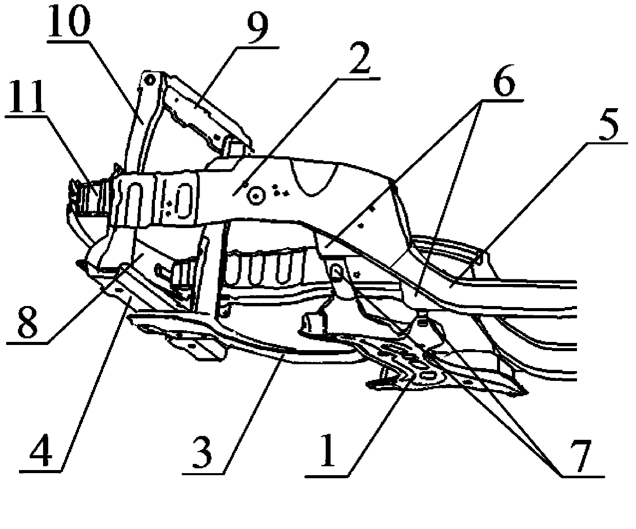
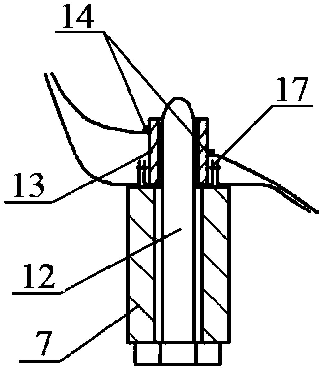
[0027] Such as figure 1 , figure 2 with image 3 As shown, the installation structure of this embodiment includes a reinforcement bracket 6 connected to the longitudinal beam of the vehicle body and a reinforcement bracket 6 connected to the front subframe 1 and the reinforcement bracket 6 and can be separated from the reinforcement bracket 6 under the tension exerted by the front subframe 1 of the shedding components. The installation structure is respectively arranged at the four corners of the front subframe 1, and the front subframe 1 has a reinforcement bracket 6 corresponding to each of the four corners, and the four reinforcement brackets 6 are respectively installed on the front longitudinal beams on both sides of the vehicle body. 2 and the downward bending longitudinal beam 5, the reinforcing bracket 6 is connected with the front longitudinal beam 2 and the downward bending longitudinal beam 5 by spot welding. Since the connection between the reinforcing bracket ...

Embodiment 2

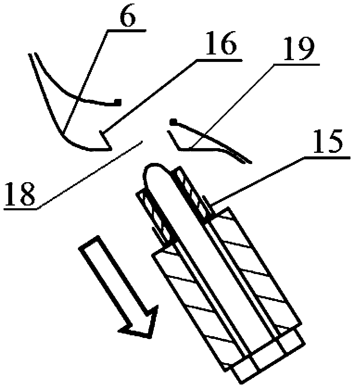
[0034] Such as figure 1 , Figure 4 , Figure 5 with Image 6 As shown, the installation structure of this embodiment includes a reinforcement bracket 6 connected to the longitudinal beam of the vehicle body and a reinforcement bracket 6 connected to the front subframe 1 and the reinforcement bracket 6 and can be separated from the reinforcement bracket 6 under the tension exerted by the front subframe 1 of the shedding components. The installation structure is respectively arranged at the four corners of the front subframe 1, and the front subframe 1 has a reinforcement bracket 6 corresponding to each of the four corners, and the four reinforcement brackets 6 are respectively installed on the front longitudinal beams on both sides of the vehicle body. 2 and the downward bending longitudinal beam 5, the reinforcing bracket 6 is connected with the front longitudinal beam 2 and the downward bending longitudinal beam 5 by spot welding. Since the connection between the reinfor...


PUM


Abstract

The invention discloses an automobile front auxiliary frame installing structure. A front auxiliary frame is installed on an automobile body longitudinal girder through the installing structure, and compared with the prior art, the installing structure can automatically fall off to separate the front auxiliary frame and the automobile body longitudinal girder when an automobile collides. Influence on the deformation mode of the automobile body longitudinal girder is reduced, the acceleration peak value of the automobile body is reduced, intrusion amount of a front wall plate is reduced, keeping of passenger compartment integrity is facilitated, and collision safety performance is improved. Moreover, the installing structure is simple in structure, obvious in effect and low in cost, production is easy to achieve, and part generalization is convenient to achieve.

Description

technical field [0001] The invention relates to automobile technology, in particular, the invention relates to a mounting structure for an automobile front auxiliary frame. Background technique [0002] People often refer to the collision of the car as a collision, and the collision between the human body and the interior parts of the car as the second collision. The secondary collision is caused by the rapid relative motion of the human body and the vehicle due to the primary collision. In order to protect the safety of the occupants in the car, the collision safety design of the car structure is particularly important. [0003] Nowadays, the front sub-frame of most automobiles is rigidly connected with the longitudinal beam of the body by bolts. However, the rigid connection between the subframe and the longitudinal beam will affect the deformation mode of the front longitudinal beam, so that the front longitudinal beam cannot produce ideal bending deformation, which red...

Claims


Application Information

Patent Timeline
Patent Type & Authority Applications(China)
IPC IPC(8): B62D21/00B62D21/15
Inventor 施斌
Owner CHERY AUTOMOBILE CO LTD
Why Eureka
Try Eureka