Signal offset determination and correction

A signal and background signal technology, applied in the field of signal drift determination and correction, can solve the problems of background signal changes, inaccuracy, and unreliable two-color correction technology correction technology, so as to reduce idle time, reduce complexity, and relax precision the effect of the requirements

Active Publication Date: 2018-03-13
F HOFFMANN LA ROCHE & CO AG
View PDF7 Cites 1 Cited by
  • Summary
  • Abstract
  • Description
  • Claims
  • Application Information

AI Technical Summary

Problems solved by technology

However, in some cases the background signal may change over time, e.g. after cuvette movement
This can lead to less reliable and / or less accurate two-color correction techniques and other correction techniques

Method used


Image

  • Signal offset determination and correction
  • Signal offset determination and correction
  • Signal offset determination and correction

Examples


Embodiment Construction

[0027] Methods for determining background drift in an optical measurement signal and specific aspects of analyzers that include a background drift detection module are discussed below.

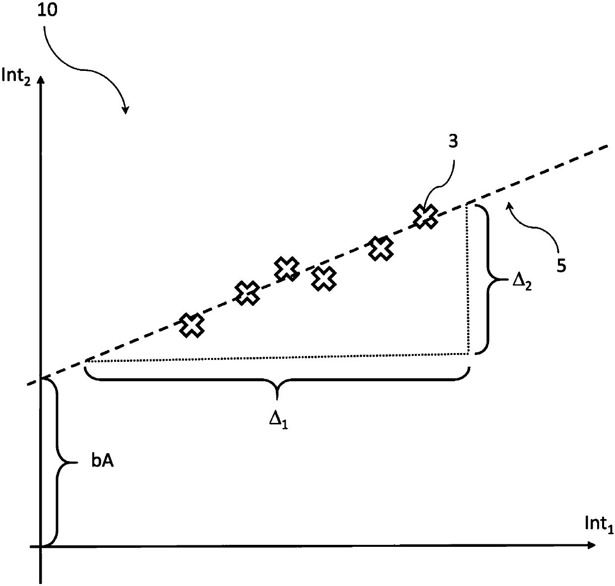
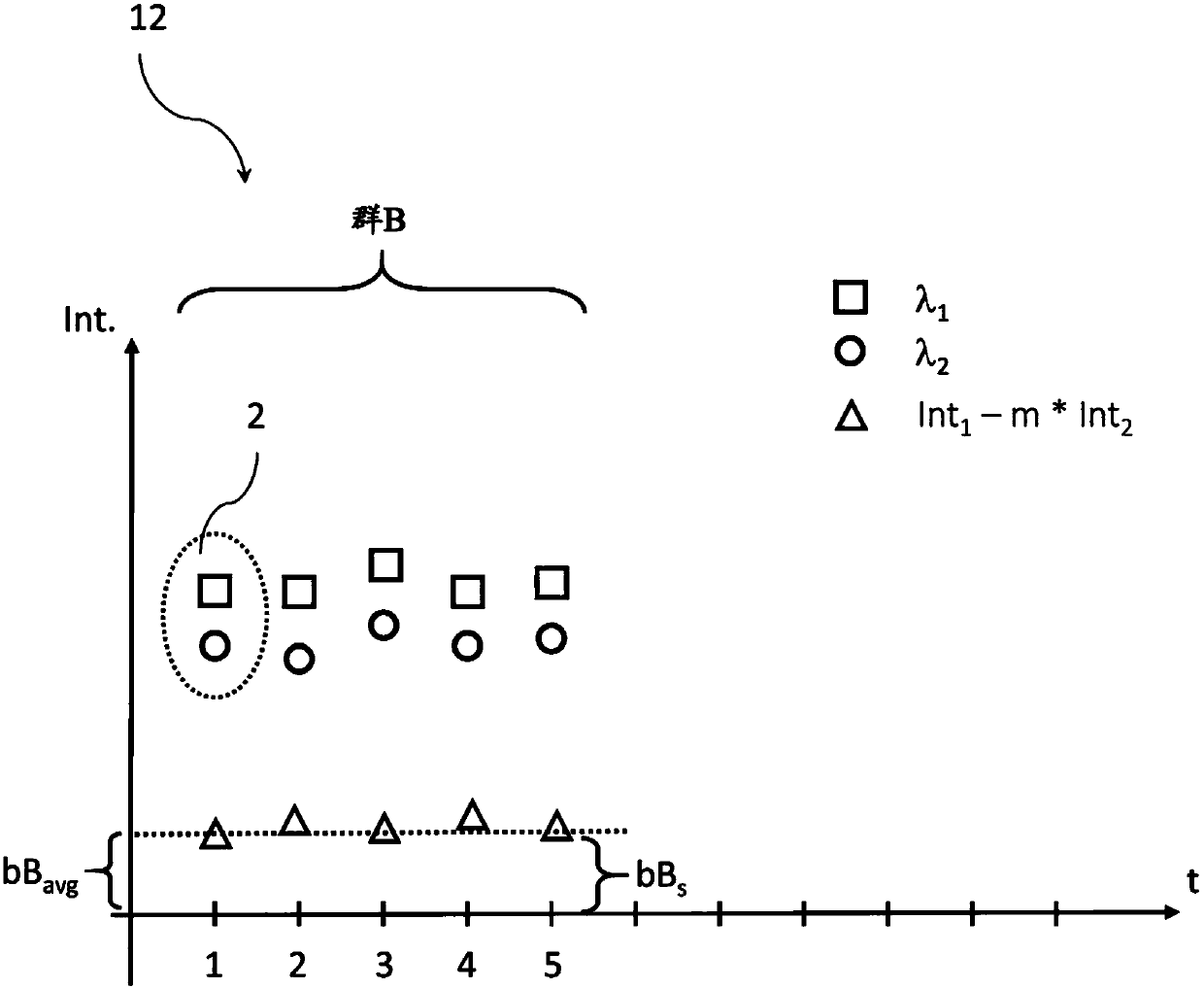
[0028] combine Figure 1 to Figure 3 , some aspects of determining and correcting background drift in optical measurement signals will be discussed. Then, combine Figure 4 to Figure 6 , different aspects of an analyzer comprising a background drift detection module according to the invention will be dealt with in more detail.

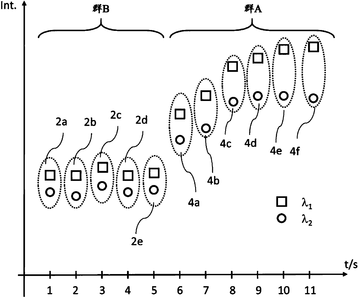
[0029] Figure 1 to Figure 3 Shown is a method for determining background drift in an optical measurement signal of, for example, a sample analyzer, the method comprising obtaining the results of a plurality of sets of optical measurements 2a-2e, 4a-4f performed on a sample by, for example, an analyzer at different points in time, Each set of measurements 2a-2e, 4a-4f includes at least one measurement obtained in the first channel (e.g. at the first wavelength λ 1 ...


PUM


Abstract

One aspect of the present disclosure relates to a method for determining a background shift, the method including obtaining a plurality of sets of optical measurements of a sample taken by the analyzer for samples at different points in time, each set including at least one measurement taken in a first channel and another measurement taken in a second channel different from the first channel, theplurality of sets of optical measurements including one group of sets and another group of sets, the measurements in the one group of sets showing a higher signal change than the measurements in the other group, determining a first background signal based on a relation of measurements in the first and second channels in the one group, determining a second background signal based on a relation of measurements in the first and second channels in the one group and the other group and determining a background shift based on the first and second background signals.

Description

technical field [0001] The invention relates to a method for determining a background drift in an optical measurement signal and an analyzer comprising a background drift detection module. Background technique [0002] Various types of optical measurement methods are used in many automated sample analyzers. For example, a clinical chemistry analyzer can be configured to measure the absorbance of a biological sample based on such a measurement method to determine single or multiple parameters of the biological sample. Optical measurements can be affected by different types of background signals. One technique for reducing the effect of background signals is the so-called two-color correction technique. This technique may involve taking measurements at two different wavelengths and subtracting the two measurements to remove the constant background signal contained in the two measurement signals. However, in some cases the background signal may change over time, for example,...

Claims


Application Information

Patent Timeline
Patent Type & Authority Applications(China)
IPC IPC(8): G01N21/01
CPCG01N21/01G01N21/253G01N21/272G01N21/274G01N21/82G01N35/00G01J3/28G01N21/03G01N35/00693G01N2201/127
Inventor R·诺伯尔
Owner F HOFFMANN LA ROCHE & CO AG
Why Eureka
Try Eureka