Fatigue experiment device based on engineering mechanics

A technology of engineering mechanics and experimental equipment, which is applied in the direction of measuring equipment, testing of mechanical components, testing of machine/structural components, etc., can solve problems such as long test time, equipment failure, and incomplete reset of spring expansion and contraction, etc., to achieve Automated operation, the effect of improving test efficiency

Inactive Publication Date: 2018-03-20
NANCHANG UNIV
View PDF4 Cites 1 Cited by
  • Summary
  • Abstract
  • Description
  • Claims
  • Application Information

AI Technical Summary

Problems solved by technology

[0002] Spring plays a pivotal role in engineering mechanics. It is a mechanical part that uses elasticity to work. Parts made of elastic materials are deformed under the action of external force and return to their original shape after removing the external force. When the spring is working, the force it receives It changes frequently. Under the action of alternating stress, although the stress it bears is lower than the yield point of the material, the phenomenon of cracks or sudden complete fracture after a long period of work is called metal fatigue, even if the spring It is not broken, but due to long-term stress, the expansion and contraction of the spring cannot be completely reset, and some work cannot be completed, resulting in equipment failure, so fatigue tests are required for different batches of springs
[0003] The spring fatigue testing machine is

Method used


Image

  • Fatigue experiment device based on engineering mechanics
  • Fatigue experiment device based on engineering mechanics
  • Fatigue experiment device based on engineering mechanics

Examples


Embodiment Construction

[0018] A specific embodiment of the present invention will be described in detail below in conjunction with the accompanying drawings, but it should be understood that the protection scope of the present invention is not limited by the specific embodiment.

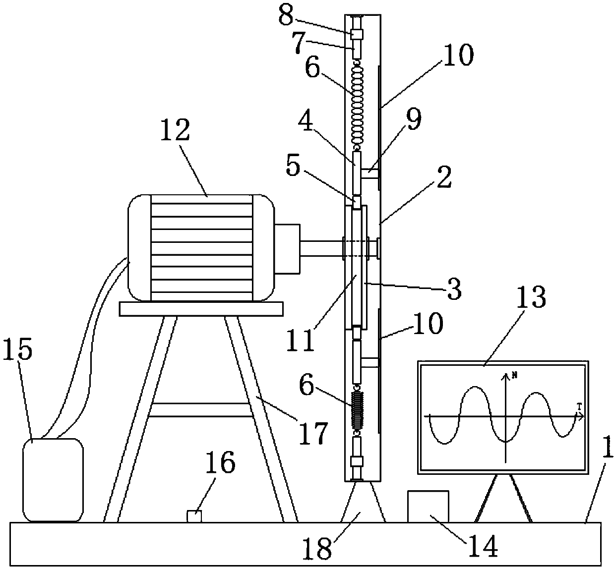
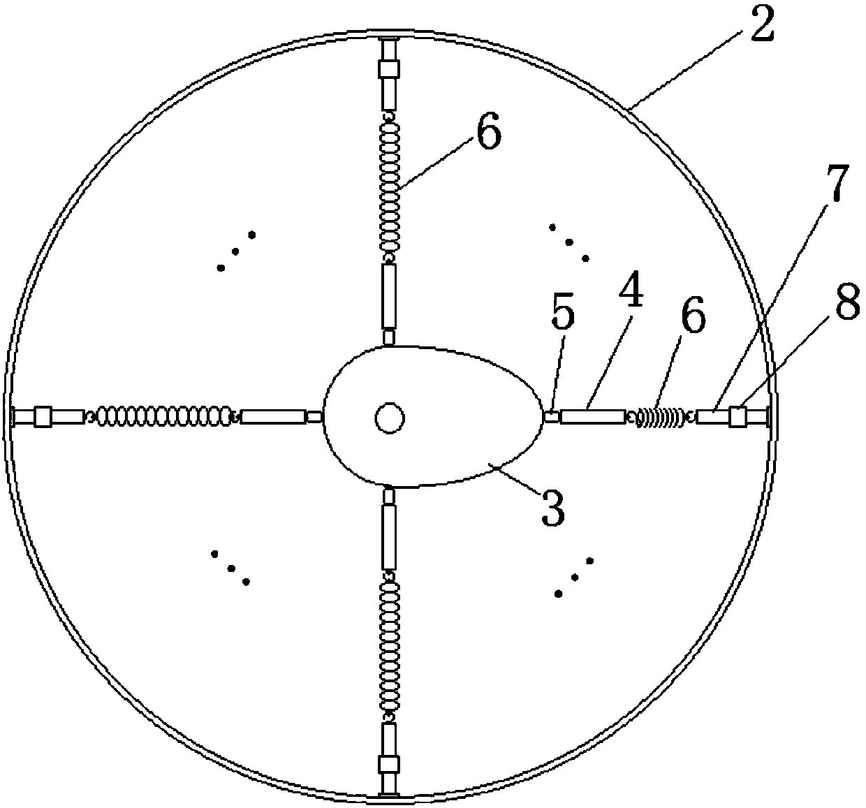
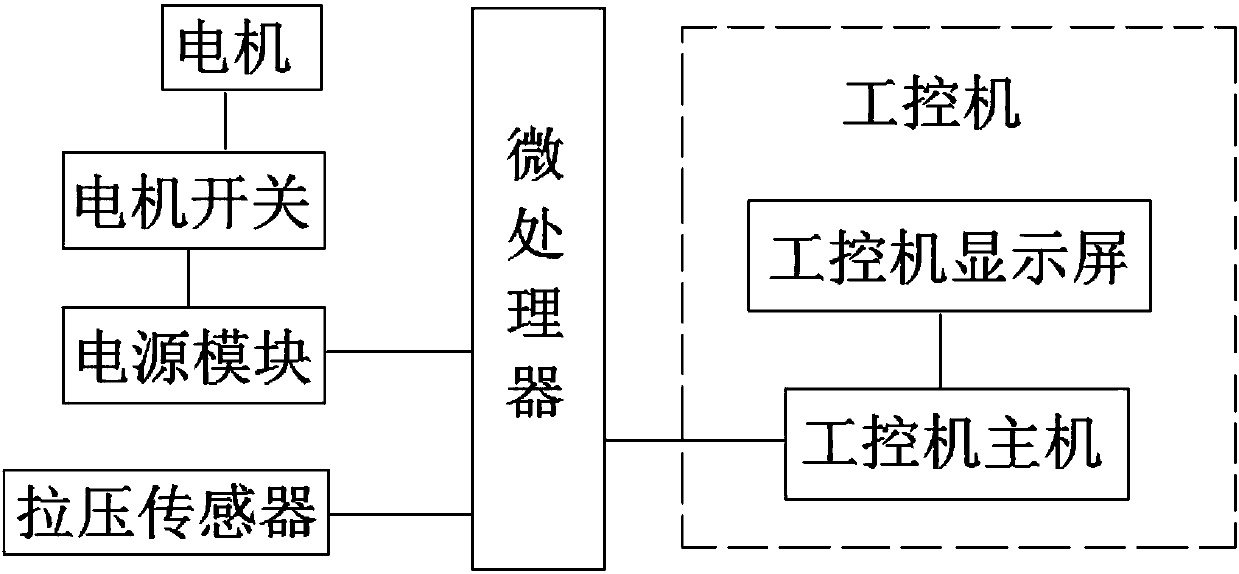
[0019] see Figure 1-Figure 3 , the embodiment of the present invention provides an engineering mechanics fatigue resistance test device, comprising a base plate 1, a disc body 2 is fixed on the base plate 1, wherein the disc surface of the disc body 2 is vertically arranged, and the disc surface is perpendicular to the surface of the base plate 1; The middle part of the disc body 2 is provided with a cam 3, the axis of the cam 3 is perpendicular to the disc surface and passes through the center point of the disc surface; the cam 3 is connected to the output shaft of the motor 12, and the motor 12 is connected to the bottom plate 1 The power module 15 on the top is electrically connected; the convex ridge of the cam 3 is p...


PUM


Abstract

The invention provides a fatigue experiment device based on engineering mechanics. The fatigue experiment device includes a disc body. A cam is arranged in the middle of the disc body. The cam is connected with a motor shaft. A T-type chute is arranged in the ridge of the cam. Multiple sliders are connected in a sliding manner to the T-type chute. Each slider is connected with a spring fatigue experiment connecting mechanism. Each spring fatigue experiment connecting mechanism includes a movable connecting body and an adjustable-length fixed connecting body. A tested spring is connected between each fixed connecting body and the corresponding movable connecting body. Each movable connecting body is connected with the corresponding slider. The middle of each fixed connecting body is correspondingly connected with a tension and pressure sensor. The tension and pressure sensors are in signal connection with an industrial personal computer through a microprocessor. Fatigue experiment can be carried out on a plurality of springs or springs of a variety of specifications simultaneously, and the test efficiency of spring fatigue experiment is greatly improved. Moreover, the force condition of a detected spring in experiment can be fed back in real time, and automatic operation of the whole test process can be realized.

Description

technical field [0001] The invention relates to the field of fatigue resistance experiments of mechanical parts, in particular to a fatigue resistance experiment device of engineering mechanics. Background technique [0002] Spring plays a pivotal role in engineering mechanics. It is a mechanical part that uses elasticity to work. Parts made of elastic materials are deformed under the action of external force and return to their original shape after removing the external force. When the spring is working, the force it receives It changes frequently. Under the action of alternating stress, although the stress it bears is lower than the yield point of the material, the phenomenon of cracks or sudden complete fracture after a long period of work is called metal fatigue, even if the spring It is not broken, but due to the long-term stress, the expansion and contraction of the spring cannot be completely reset, and some work cannot be completed, resulting in equipment failure. Th...

Claims


Application Information

Patent Timeline
IPC IPC(8): G01M13/00
CPCG01M13/00
Inventor 晏洪张雷黄模佳兰志文
Owner NANCHANG UNIV
Why Eureka
Try Eureka