Description method of turbidite reservoir with high sand ratio

A turbidite and reservoir technology, applied in seismology, seismic signal processing, geophysical measurement, etc., can solve the problems of rapid changes in lithofacies, difficulty in finding out the distribution and deposition characteristics of sand bodies, and difficulty in identification. Achieve accurate developmental and distributional characteristics

Active Publication Date: 2020-07-14
CHINA PETROLEUM & CHEM CORP +1
View PDF11 Cites 0 Cited by
  • Summary
  • Abstract
  • Description
  • Claims
  • Application Information

AI Technical Summary

Problems solved by technology

However, the turbidite sediments developed in continental lake basins are complex in development, lithofacies change rapidly, and there are overlapping phenomena.
With the deepening of exploration, large-scale turbidite bodies that are easily identifiable seismically have been basically recognized; some turbidites that overlap each other, have thin mudstone barriers between adjacent sand bodies, and relatively high sandy ground are often not visible on seismic sections. It is easy to identify, but it is difficult to find out the distribution shape and sedimentary characteristics of sandbodies directly from the interpretation of seismic data and conventional inversion results
The previous geophysical techniques (such as conventional seismic description, attribute extraction, etc.) used to find large-scale and easily identifiable seismic traps are no longer suitable for increasingly complex types of turbidite lithologic traps, which affects the overall exploration deployment. and reserve upgrade evaluation

Method used


Image

  • Description method of turbidite reservoir with high sand ratio
  • Description method of turbidite reservoir with high sand ratio
  • Description method of turbidite reservoir with high sand ratio

Examples


Embodiment Construction

[0021] In order to make the above and other objects, features and advantages of the present invention more comprehensible, the preferred embodiments are listed below and shown in the accompanying drawings in detail as follows.

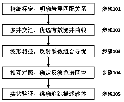
[0022] Such as figure 1 as shown, figure 1 It is a flow chart of the method described for the high-sand ratio turbidite reservoir of the present invention.

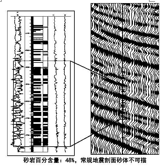
[0023] Step 101, fine synthetic record calibration, clarifying the corresponding relationship between lithology and seismic reflection features. In the seismic workstation, through fine synthetic record calibration, the corresponding relationship between lithology and seismic reflection characteristics is clarified, and the descriptive probability of high-sand ratio turbidite reservoirs on conventional seismic sections is analyzed. In one embodiment, the seismic data of the 3D seismic data in the target layer where the research area is located has a narrow frequency band, a low main frequency, a...


PUM


Abstract

The invention provides a description method of a turbidite reservoir with a high sandstone-stratum ratio. The method comprises steps of step 1, carrying out fine synthetic recording calibration and explicating a corresponding relation between lithological characteristics and seismic reflection characteristics; step 2, carrying out multi-well crossploting analysis and optimally selecting a well measuring curve capable of effectively distinguishing sand shale; step 3, by use of the effective well measuring curve, carrying out reservoir reversion under waveform indication; step 3, based on the well, carrying out mutual comparison and careful analysis on the well participating in the reversion and determining reversion chromatography blocks; and step 5, carrying out comparison verification onreal drilling sand bodies of wells which participate in and fail to participate in the reversion with well side reversion channels, and carrying out accurate tracking description on the sand bodies byusing the reversion and drilling data. According to the invention, sand body shapes matching with the actual depositional characteristics can be accurately and quickly described; and growth and distribution characteristics of the turbidite can be quite precisely reflected.

Description

technical field [0001] The invention relates to the technical field of petroleum exploration, in particular to a method for describing high-sand ratio turbidite reservoirs. Background technique [0002] For high-sand ratio turbidite reservoirs, there is a lack of systematic research methods for overall description using seismic data, and there are problems of "missing" reservoirs and multi-solutions in descriptions. A method for characterization of turbidite reservoirs. [0003] In recent years, turbidite exploration in Shengli Oilfield has achieved great success, and turbidite reservoirs have become an important position for increasing reserves in the near future. However, the turbidite sedimentary bodies developed in continental lake basins are complex in development, lithofacies change rapidly, and overlap each other. With the deepening of exploration, large-scale turbidite bodies that are easily identifiable seismically have been basically recognized; some turbidites t...

Claims


Application Information

Patent Timeline
Patent Type & Authority Patents(China)
IPC IPC(8): G01V1/30
CPCG01V1/306G01V2210/6163G01V2210/6167G01V2210/6169G01V2210/624G01V2210/64
Inventor 徐昊清王永诗马立驰郭玉新景安语孙超张明华辛也王婵许晓凤秦永霞王莉庄梅孙锡文毕俊凤王亚琳熊伟杨贵丽
Owner CHINA PETROLEUM & CHEM CORP
Why Eureka
Try Eureka