Communication cable connection device

A wiring device and communication cable technology, which is applied to two-part connection devices, parts of connection devices, coupling devices, etc., can solve problems such as time-consuming, waste of resources, waste of resources, etc., to improve connection stability, Improve wiring efficiency and reduce waste of resources

Inactive Publication Date: 2018-03-23
安徽恒源煤电股份有限公司
View PDF7 Cites 0 Cited by
  • Summary
  • Abstract
  • Description
  • Claims
  • Application Information

AI Technical Summary

Problems solved by technology

[0002] At present, in the field of communication, a cable core composed of multiple insulated wires is often used. When the communication cable is not long enough and an additional extension cable needs to be connected, in order to ensure the normal information transmission function, it is often necessary to insulate the insulation in the cable core. The wires are connected correspondingly. The traditional communication cable butt joint method is to peel off the insulation skin at the end of the insulated wire, wrap the stripped two corresponding wires together, and use insulating tape to wrap around the exposed part of the connection between the two wires. , use this method to connect all the insulated wires separately. It takes a lot of time to peel and wrap the wires in this way, and it consumes a lot of energy for the operator. When it is necessary to separate the connection, it is usually because the separation operation is more complicated. Cutting off the cable at the connection directly will shorten the length of the cable and waste resources. Now the commonly used cable connection device is to use the terminal to connect the communication cable. After the co

Method used


Image

  • Communication cable connection device
  • Communication cable connection device
  • Communication cable connection device

Examples


Embodiment Construction

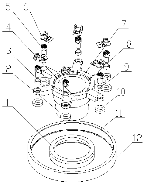
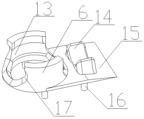
[0022] A communication cable connection device of the present invention is realized in this way. When in use, the two present inventions are used in combination, and the connection end of the communication cable is sequentially passed through the sealing sleeve (2), the fixing cylinder (4) and the fixing ring (7 ), then remove the insulation layer at the connection end, pass each insulated wire in the communication cable through a plurality of limiting slots (8) one by one, then pass through the corresponding two limiting blocks (14), and finally get stuck in the corresponding Between the two adjacent conductive sheets (18) on the rotating block (5), then rotate the sealing sleeve (2), and the sealing sleeve (2) drives the fixed ring (7) to rotate through the fixed cylinder (4), and then drives multiple The roller (10) rotates, the roller (10) rotates along the inner wall of the sleeve (12), the friction pad (11) on the inner wall of the roller (10) and the sleeve (12) generate...


PUM


Abstract

The invention relates to a communication cable connection device and discloses a connection device for correspondingly connecting respective insulated wires in two connected communication cables. Thecommunication cable connection device is characterized in that a fixing cylinder is placed in the middle of the bottom end of a sleeve by a fixing bearing; a sealing sleeve is placed at the bottom ofthe fixing cylinder and is communicated with the fixing cylinder; a fixing ring is placed on the top of the fixing cylinder and is placed in the sleeve; a plurality of limit slots are formed at equalintervals in the fixing ring; a plurality of connecting plates are placed at equal intervals to the outer side of the fixing ring and correspond to the plurality of limit slots respectively; the connecting plates are located in the sleeve and are provided with through holes therein; a plurality of mounting holes are formed in each connecting plate; a fixing plate is placed on each connecting platethrough a plurality of fixing rods; the plurality of fixing rods correspond to the plurality of mounting holes in each corresponding connecting plate respectively; two limiting blocks are respectively placed on each fixing plate and are placed opposite to each other, and two opposite faces on the two limiting blocks form an arc-shaped surface; and the arc-shaped surfaces have a plurality of grooves therein.

Description

technical field [0001] The invention relates to a connection device for communication cables, which relates to a connection device for connecting communication cables and belongs to the field of communication equipment. In particular, it relates to a wiring device for correspondingly connecting insulated wires in two connected communication cables. Background technique [0002] At present, in the field of communication, a cable core composed of multiple insulated wires is often used. When the communication cable is not long enough and an additional extension cable needs to be connected, in order to ensure the normal information transmission function, it is often necessary to insulate the insulation in the cable core. The wires are connected correspondingly. The traditional communication cable butt joint method is to peel off the insulation skin at the end of the insulated wire, wrap the stripped two corresponding wires together, and use insulating tape to wrap around the exp...

Claims


Application Information

Patent Timeline
IPC IPC(8): H01R13/502H01R13/02H01R24/00
CPCH01R13/02H01R13/502H01R24/005
Inventor 不公告发明人
Owner 安徽恒源煤电股份有限公司
Why Eureka
Try Eureka