Sealing part for split type pump provided with sealed oil path
A split type and seal technology, which is applied to pump components, parts of pumping devices for elastic fluids, non-variable pumps, etc., can solve inconvenient loading and unloading, limited safety and firmness, and limited sealing and other issues to achieve the effects of reducing occupation, improving firmness and stability, and improving sealing
- Summary
- Abstract
- Description
- Claims
- Application Information
AI Technical Summary
Problems solved by technology
Method used
Image

Examples
Embodiment Construction
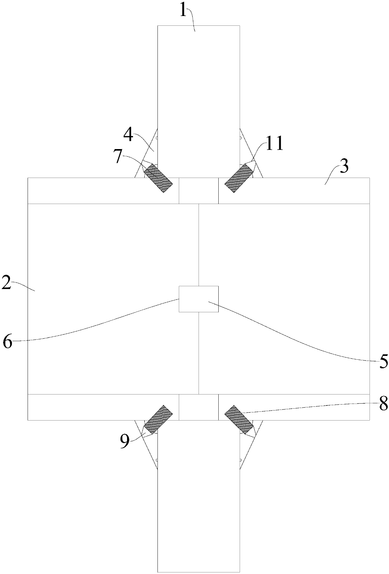
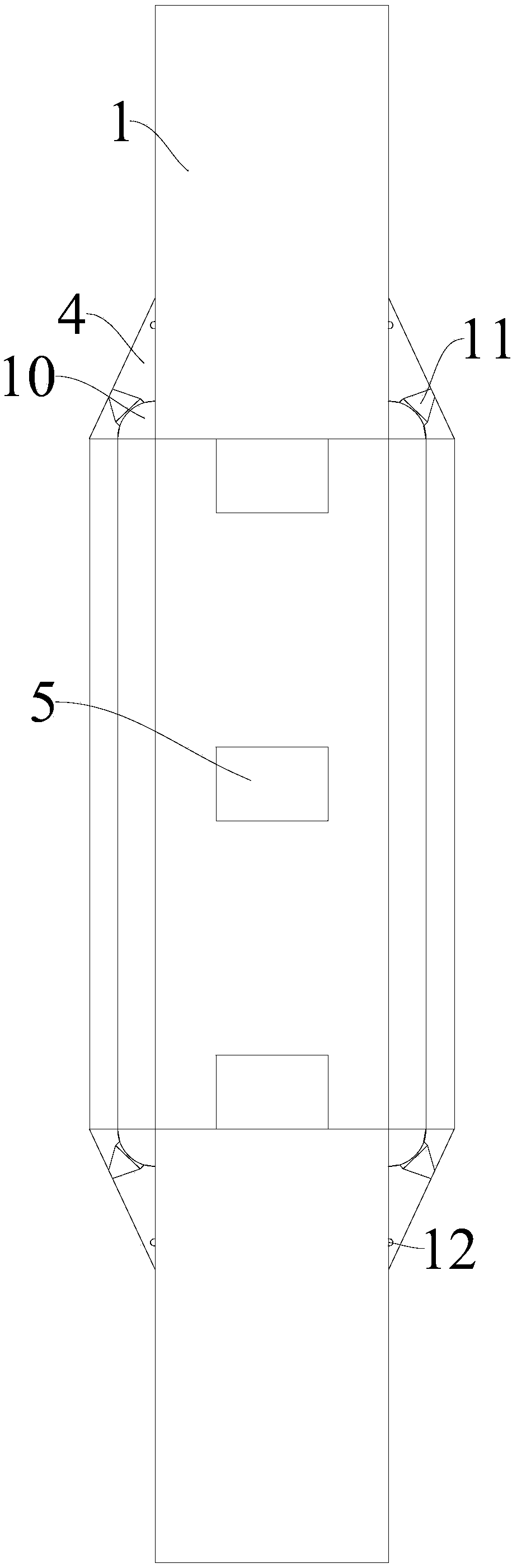
[0013] The present invention is described in further detail now in conjunction with accompanying drawing. These drawings are all simplified schematic diagrams, which only illustrate the basic structure of the present invention in a schematic manner, so they only show the configurations related to the present invention.
[0014] figure 1 and figure 2 A split pump seal with a sealed oil passage is shown, including a central main seal ring 1, a left seal joint 2 on the left side of the main seal ring 1, and a right seal joint 2 on the right side of the main seal ring 1. Sealing connector 3, the left side and right side of the main sealing ring 1 are located at the openings on both sides of the inner through hole, and both have an integrated structure that improves the sealing of the assembly position. Lateral sealing ring 4, and the lateral sealing ring 4 is close to the main sealing ring 1 The outer surface is a slope that gradually becomes lower from the inside to the outsid...
PUM
 Abstract
Description
Claims
Application Information
 - Generate Ideas
- Intellectual Property
- Life Sciences
- Materials
- Tech Scout
- Unparalleled Data Quality
- Higher Quality Content
- 60% Fewer Hallucinations
Browse by: Latest US Patents, China's latest patents, Technical Efficacy Thesaurus, Application Domain, Technology Topic, Popular Technical Reports.
© 2025 PatSnap. All rights reserved.Legal|Privacy policy|Modern Slavery Act Transparency Statement|Sitemap|About US| Contact US: help@patsnap.com