Adjustable multi-ring polarizing light reduction lens group axially positioned by elastic inserts

An adjustable, dimming mirror technology, applied in the filter, optics, camera body and other directions for photographic purposes, can solve the problem that the amount of light reduction cannot maintain a fixed amount of light reduction, damage the quality of the camera and its effect, and cannot be the first. Problems such as synchronous rotation of the pivot ring

Active Publication Date: 2021-01-05
蒙天培
View PDF12 Cites 0 Cited by
  • Summary
  • Abstract
  • Description
  • Claims
  • Application Information

AI Technical Summary

Problems solved by technology

[0006] For a long time, in addition to using the "three-ring polarizing light-reduction lens group" personally, the inventor also actively shared various photography experiences and experiences with related common fans. During the aforementioned process, he found that although the aforementioned "three-ring The polarized light reduction lens set" not only allows consumers to freely adjust the passing rate of incident light, but also has the effect of polarizing filters to filter specific polarized light. However, consumers do not need to adjust the amount of light reduction in most shooting environments , and only want to adjust the passing angle of specific polarized light, in order to effectively eliminate the reflection on the surface of the subject (such as: water surface, window glass or plant leaf surface), and obtain the ideal shooting effect. However, when using the aforementioned "three-ring When adjusting the polarization angle of the polarizing and light-reducing lens group of the formula, the first pivot ring and the second pivot ring are designed to be able to rotate independently of each other relative to the camera lens, and the two are adjacent to each other. As a result, when the first pivotal ring (or the second pivotal ring) is rotated, it is very easy to touch the second pivotal ring (or the first pivotal ring) by mistake, or it is impossible to make the first pivotal ring and the first pivotal ring The second pivot ring maintains stable synchronous rotation, so that the angle between the polarization angles of the polarizing lenses cannot be maintained at a fixed value, and the amount of light reduction cannot be maintained at an expected fixed amount of light reduction, which will damage the image. Quality and its effects

Method used


Image

  • Adjustable multi-ring polarizing light reduction lens group axially positioned by elastic inserts
  • Adjustable multi-ring polarizing light reduction lens group axially positioned by elastic inserts
  • Adjustable multi-ring polarizing light reduction lens group axially positioned by elastic inserts

Examples


Embodiment Construction

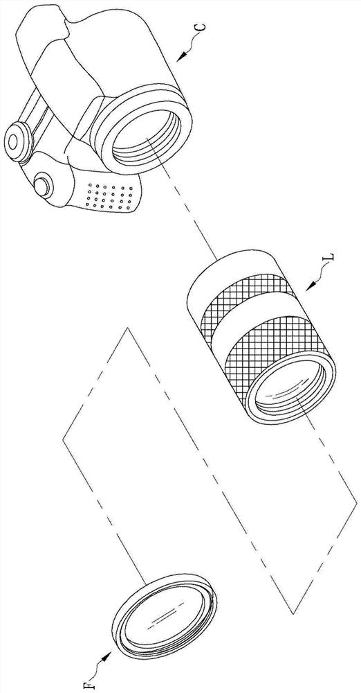
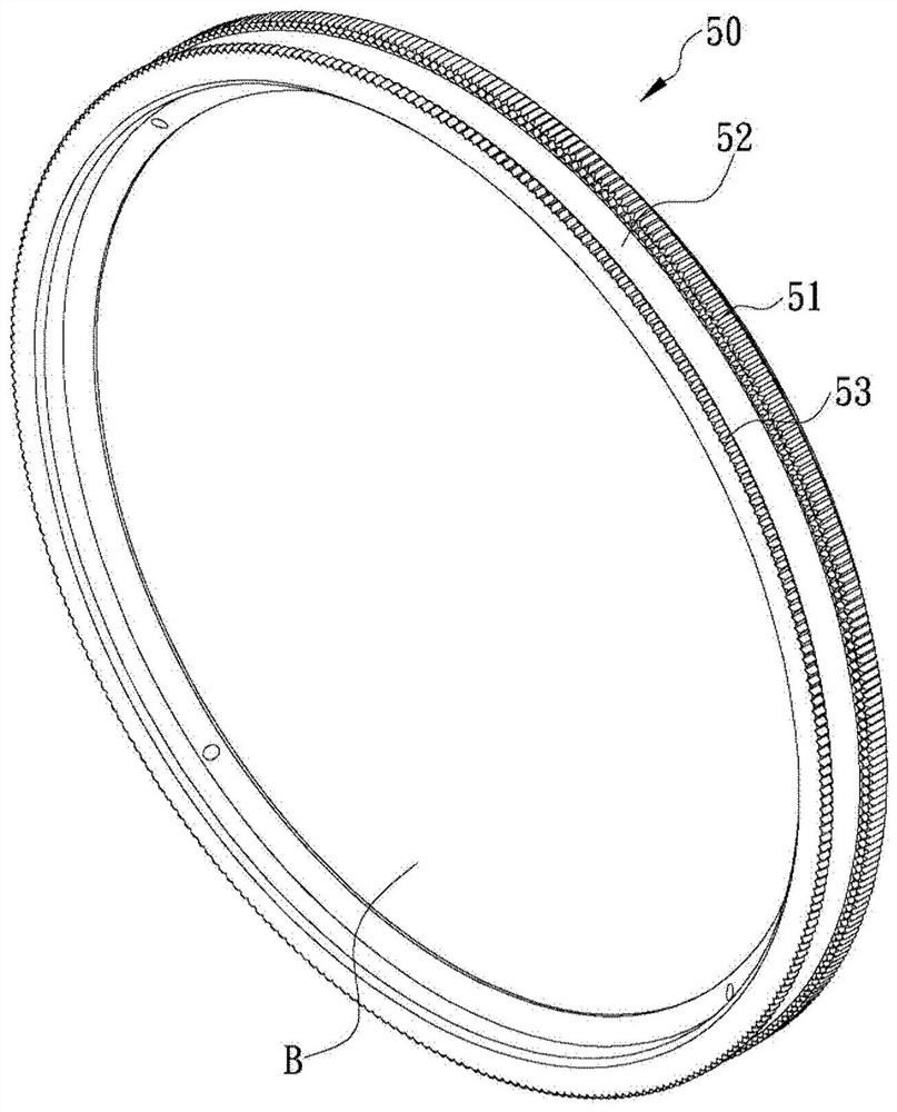
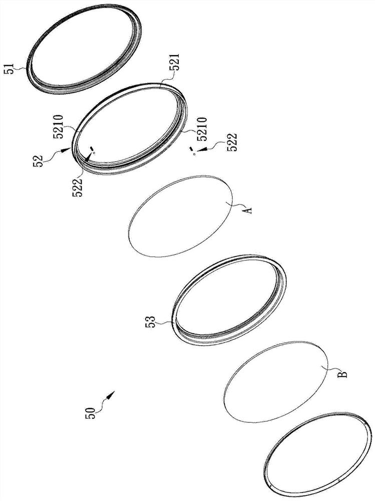
[0046] In a first preferred embodiment of the invention, see figure 2 As shown, there is provided an adjustable three-ring polarized light-reducing lens group 50 axially positioned by an elastic insert, and the three-ring polarized light-reducing lens group 50 is applied to a camera lens L (such as figure 1 shown), and can be attached to a camera C along with the camera lens L (such as figure 1 shown). In this first preferred embodiment, see figure 2 and image 3 As shown, the three-ring polarized light reduction lens group 50 includes a fixed ring 51, a first pivot ring 52, a first polarizing lens A, a second pivoting ring 53 and a second polarizing lens B, wherein , see image 3 and Figure 4 As shown, the fastening ring 51 is a hollow circular ring frame, one end of which is protruded with a threaded ring 511 along the axial direction, and the radial outer edge of the threaded ring 511 is provided with threads 5110. The screw thread 5110 of 511 can be screwed with t...


PUM


Abstract

The present invention is an adjustable multi-ring polarized light-reduction lens group axially positioned by elastic inserts, including a fixed ring, in which a first polarized lens is fixed, one end of which can be screwed and fixed to the front of the camera lens The other end face of the edge is recessed with at least one accommodation groove along the axial direction, and an elastic inserting part is installed in the accommodation groove. The elastic inserting part can expose the free end of the accommodation groove due to its own elastic force, or Because the free end bears external force, it is embedded into the accommodating groove; a first pivot ring, in which a second polarized lens is fixed, one end of which is pivotally connected to the other end of the fixed ring, and the end surface is along the circumference An abutting portion is provided in the direction, so that the free end of the elastic embedded part can abut against an abutting groove recessed on the abutting portion. In this way, effects of different light reduction amounts can be produced, and they will not be deviated due to shaking.

Description

technical field [0001] The present invention relates to a multi-ring polarizing and light-reducing lens group, especially an adjustable multi-ring polarizing and light-reducing lens group that is axially positioned by elastic inserts, so that the two polarizing lenses set therein can be adjusted according to the user's requirements. They rotate relative to each other to easily adjust different light reduction amounts and position the light reduction amount firmly at the required light reduction value, thereby effectively improving the convenience, accuracy, stability and practicality of use. Background technique [0002] With the rapid development of digital technology, all kinds of digital products not only continue to improve in terms of efficacy and performance, but also gradually become popular as the price drops. Here is the current digital camera as an example. Due to its advantages of real-time imaging, Moreover, the images are stored digitally, which not only enables...

Claims


Application Information

Patent Timeline
Patent Type & Authority Patents(China)
IPC IPC(8): G03B11/00G03B17/14
CPCG03B11/00G03B17/14
Inventor 蒙天培
Owner 蒙天培
Why Eureka
Try Eureka