
Slide device

A sliding device and sliding part technology, applied in the direction of linear motion bearings, shafts and bearings, bearings, etc., can solve the problems of complex structure of sliding parts and decline in durability of sliding parts, so as to achieve easy combination and separation, and prevent durability. The effect of lowering and simplifying the combined structure

Active Publication Date: 2018-03-27
SEGHERS CO LTD
View PDF7 Cites 1 Cited by
  • Summary
  • Abstract
  • Description
  • Claims
  • Application Information

AI Technical Summary

Problems solved by technology

[0006] That is, according to the foregoing, the conventional sliding device not only has the disadvantage that the slider structure becomes more complicated than specified, but also the rod end of the buffer member and the transfer pin are combined with the slider, so when the reciprocating movement is performed for a long time, there is also a problem. Disadvantages of reduced durability of sliders

Method used


Image

  • Slide device
  • Slide device
  • Slide device

Examples


Embodiment Construction

[0023] Hereinafter, embodiments of the present invention will be described in more detail with reference to the drawings. However, the present invention is not limited to the embodiments disclosed below, but is realized in a variety of forms that are different from each other, but this embodiment is used to make the disclosure of the present invention complete, and can make the technical field of the present invention Those of ordinary skill fully understand the scope of the invention. In the drawings, the same reference numerals denote the same structural elements.

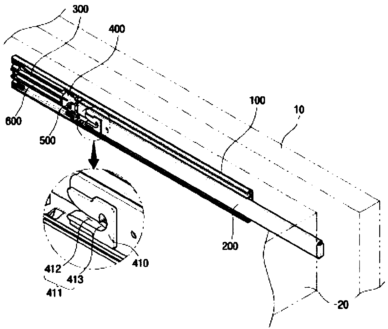
[0024] The sliding device in the preferred embodiment of the present invention can make electronic products, specifically, drawers of drawer refrigerators or various furniture, slide smoothly forward and backward. Specifically, the present invention adopts the following structure: the user pushes the storage body in the drawing-out state, so that the storage body can be self-closing (self-closing) relative to th...


PUM


Abstract

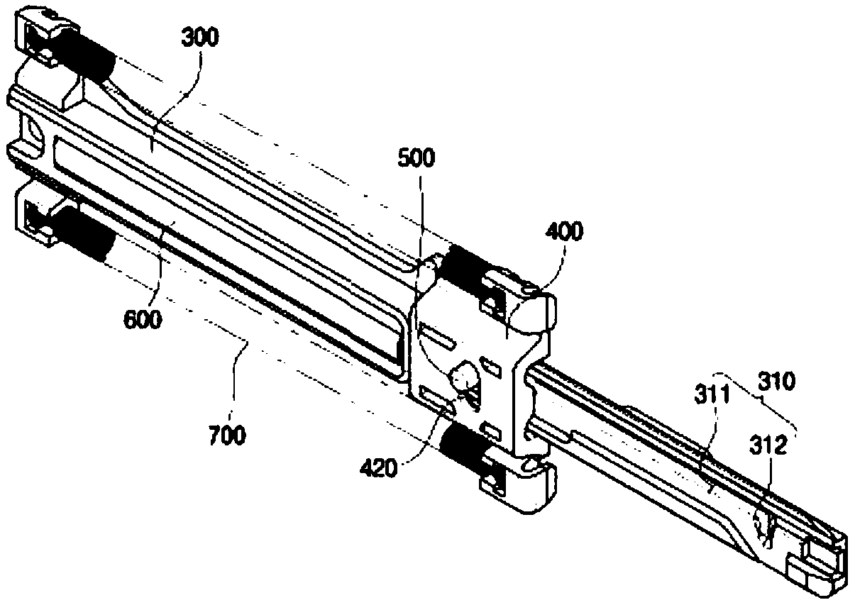
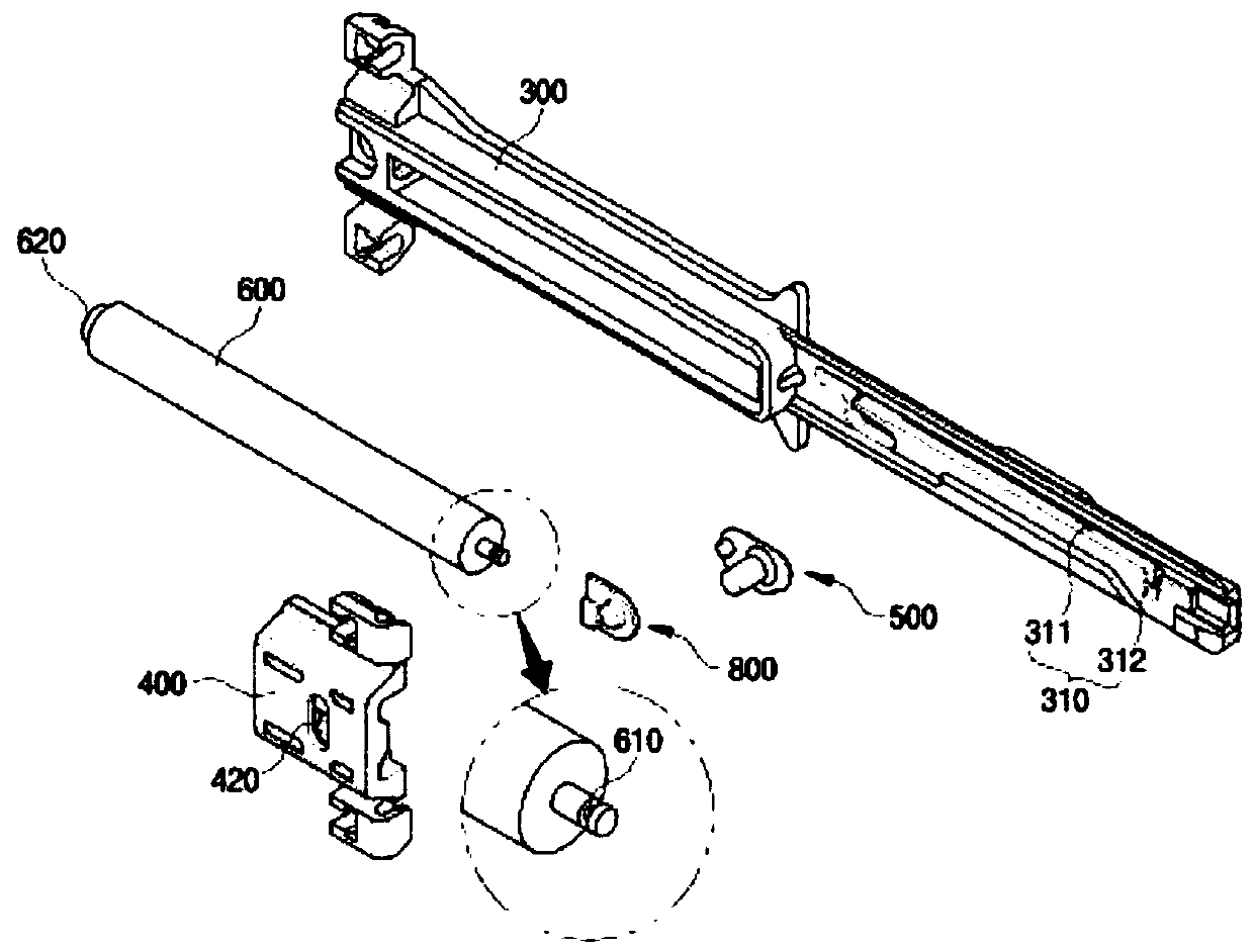
Disclosed is a slide device. The slide device of the present invention comprises: a body which is provided at one side end region of a fixed rail and has a guide path; a slider which is coupled to thebody and is selectively slidably movable along the lengthwise direction of the body during the slidable movement of a transfer rail; a transfer pin which is coupled to the slider so as to be movablesimultaneously at the time of the movement of the slider and is movable along the guide path; and a damper which is provided on the body and of which the rod end part is provided so as to be connectedwith the transfer pin. The present invention employs a structure in which the rod end part of the damper is separably coupled to a sub transfer pin without being directly coupled to the slider, and thereby can maximally prevent occurrence of a problem wherein the durability of the slider degrades during long-term reciprocating movement.

Description

technical field [0001] The present invention relates to a sliding device, and more specifically, to a sliding device having a structure in which a sub-transfer pin is provided between a transfer pin and a buffer member, and the sub-transfer pins are detachably combined with the transfer pin and the buffer member, respectively, And rotatably combined with the transfer pin. Background technique [0002] Usually, the sliding storage body is slidably provided on the main body of furniture, refrigerators, or various sorting boxes in a sliding manner so as to store required items. [0003] In the sliding storage body, a storage body installation space is provided on the main body, and the opening and closing operation is performed by a sliding device. Contact (Rolling Contact) to slide. [0004] This sliding device includes: a fixed guide rail, which is fixedly arranged on the body; a transfer guide rail, which can slide relative to the fixed guide rail, and is used to induce th...

Claims


Application Information

Patent Timeline
Patent Type & Authority Applications(China)
IPC IPC(8): A47B88/00A47B88/473A47B88/493
CPCA47B88/467A47B2210/0091A47B88/49A47B88/483A47B88/477F16C29/02
Inventor 金德会张炳千
Owner SEGHERS CO LTD
Learn More