Monitoring device for a disk brake of a motor vehicle

A disc brake and monitoring device technology, which is applied to the parts of the brake, the type of the brake, mechanical equipment, etc., can solve the problems of inaccurate measurement, high cost, and difficult orientation of the Hall sensor, so as to reduce manufacturing costs and replaceability simplified effect

Active Publication Date: 2018-03-27
WABCO EURO BVBA SPRL
View PDF7 Cites 6 Cited by
  • Summary
  • Abstract
  • Description
  • Claims
  • Application Information

AI Technical Summary

Problems solved by technology

Implementing such tubes magnetically and uniformly over large lengths is very costly, which can lead to inaccurate measurements when the magnetic field inside the tube varies
Furthermore, the introduction of elongated tubes into the readjustment device is complex, so that replacement or retrofitting is associated with high installation costs
In addition, the orientation of the magnet tube relative to the Hall sensor in the reorientation device is difficult

Method used


Image

  • Monitoring device for a disk brake of a motor vehicle
  • Monitoring device for a disk brake of a motor vehicle
  • Monitoring device for a disk brake of a motor vehicle

Examples


Embodiment Construction

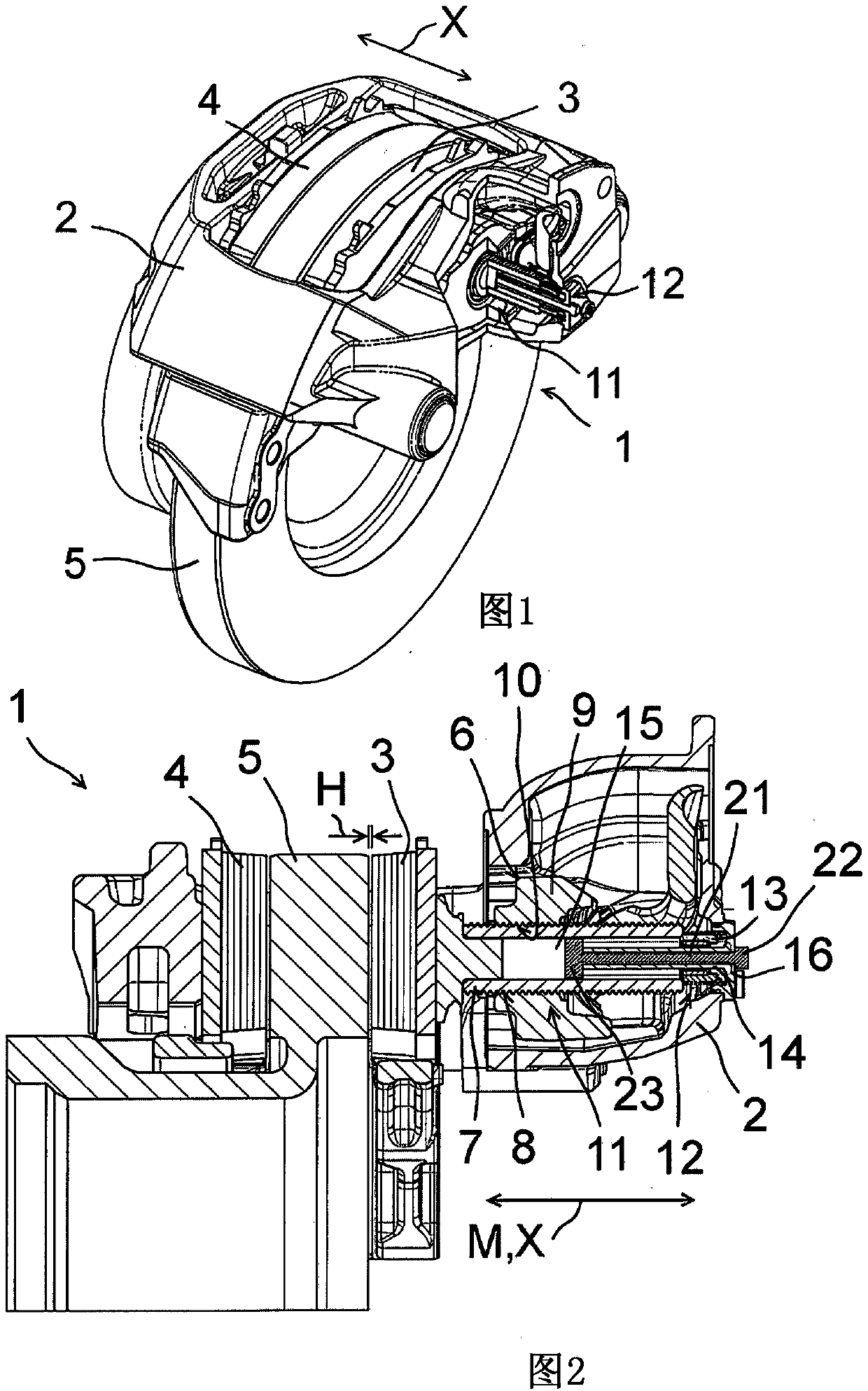
[0045] exist figure 1 The disc brake 1 is shown in a perspective view. The disc brake 1 has a brake caliper 2 , brake linings 3 , 4 and a brake disc 5 connected to a wheel to be decelerated, the brake disc being partially surrounded by the brake caliper 2 . The brake linings 3, 4 can be adjusted in the direction of movement X, so that according to a brake value generator, not shown, the brake linings 3, 4 can be pressed against the brake disc 5 in order to induce the desired speed of the wheel to be decelerated. required braking.

[0046] figure 2 A simplified sectional illustration of the disk brake 1 is shown, only relevant sections of the disk brake 1 being shown. In the released position of the disc brake 1 , the brake linings 3 , 4 are spaced apart from the brake disc 5 by the braking travel distance H. The braking stroke H represents the distance traveled by the brake linings 3, 4 from the released position without actuating the brake value generator to the image ...


PUM


Abstract

The invention relates to a monitoring device (12) for a disk brake (1), said monitoring device at least comprising: a sensor unit (14) for attachment to a brake caliper (2) of a disk brake (1) and a measuring element (13), wherein the sensor unit (14) is configured to detect a relative position of the measuring element (13), said measuring element being movable relative to the sensor unit (14), wherein the sensor unit (14) and the measuring element (13) are spaced apart from one another for forming a contact-less monitoring device (12). According to the invention, a biasing element (17) is arranged between the measuring element (13) and the sensor unit (14) for biasing the measuring element (13) against a pressure spindle (7) of the disk brake (1).

Description

technical field [0001] The invention relates to a monitoring device for a disk brake for monitoring the relative position of brake linings of the disk brake and to a disk brake, in particular a disk brake for a motor vehicle. Background technique [0002] Disc brakes in motor vehicles have brake linings which, depending on the actuation of the brake value generator, are pressed by a pressure spindle onto the brake disc connected to the wheel to be decelerated, so that the braking effect can be transmitted onto the brake discs and wheels. Such brake linings are subject to wear when using disc brakes, that is to say their thickness decreases. Thus, the braking travel of the brake lining, that is to say the passage of the brake lining from the released position in which the brake value generator is not actuated to the braking position with the brake value generator actuated The distance is extended in order to achieve the braking effect. [0003] In order to achieve a fast b...

Claims


Application Information

Patent Timeline
Patent Type & Authority Applications(China)
IPC IPC(8): F16D65/56F16D66/02
CPCF16D65/567F16D66/021F16D2066/003F16D66/00
Inventor 迈克尔·约翰马丁·斯顿夫
Owner WABCO EURO BVBA SPRL
Why Eureka
Try Eureka