Crystal piece and crystal oscillator

一种水晶振子、水晶片的技术,应用在电气元件、阻抗网络等方向,能够解决副振动、串联电阻值易增大、振动泄漏等问题,达到减少CI值的效果

Active Publication Date: 2018-03-27
MURATA MFG CO LTD
View PDF14 Cites 0 Cited by
  • Summary
  • Abstract
  • Description
  • Claims
  • Application Information

AI Technical Summary

Problems solved by technology

However, if the crystal plate is miniaturized, the influence of secondary vibration or the influence of vibration leakage will appear more significantly, or the value of series resistance will easily increase.

Method used


Image

  • Crystal piece and crystal oscillator
  • Crystal piece and crystal oscillator
  • Crystal piece and crystal oscillator

Examples


Embodiment Construction

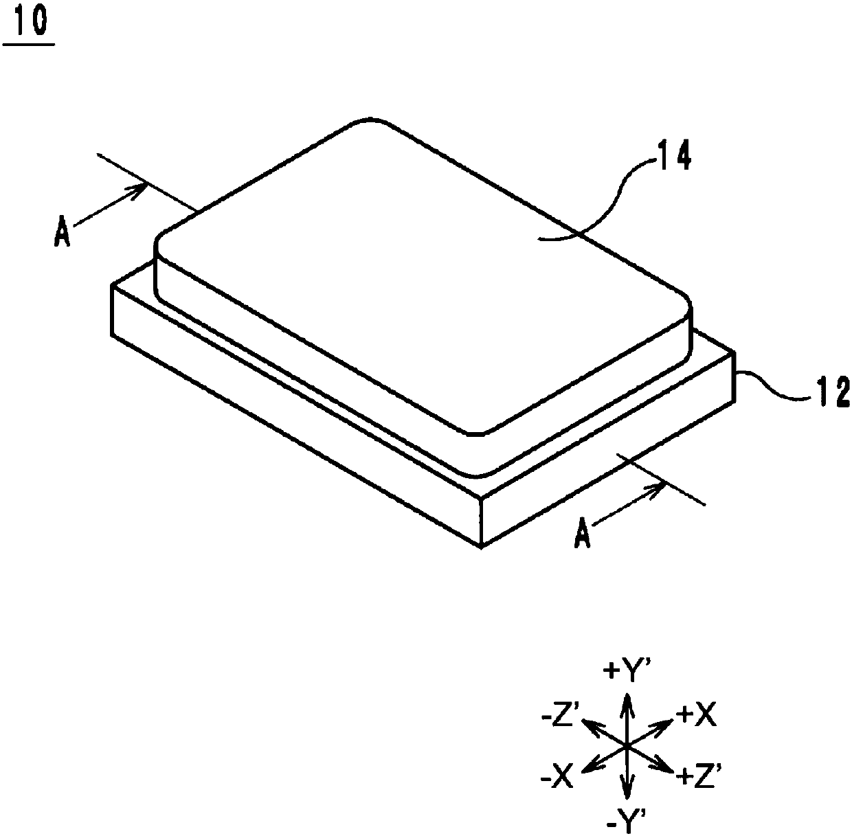
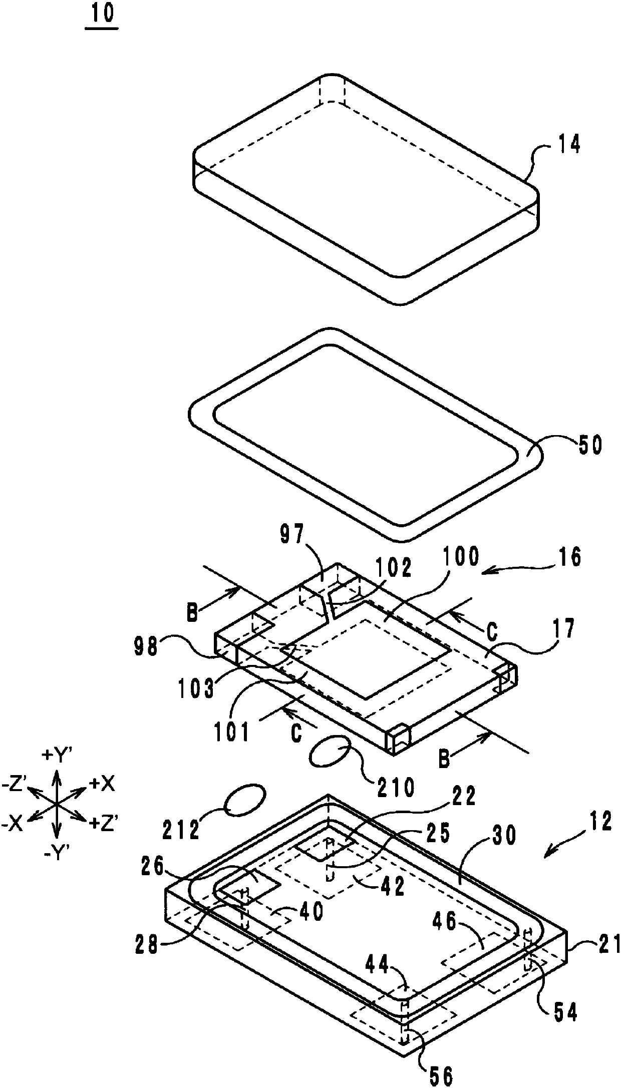
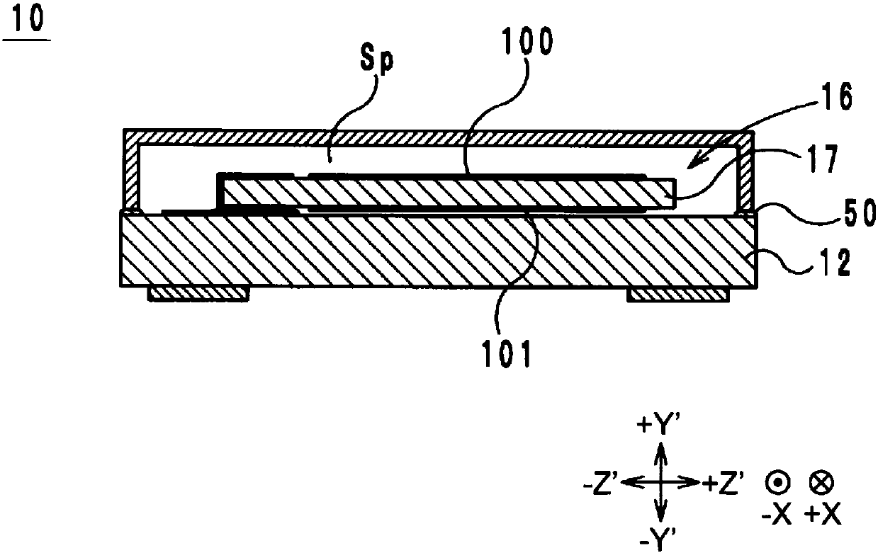
[0025] (Structure of Crystal Vibrator)

[0026] Hereinafter, a crystal vibrator including a crystal chip which is one embodiment of the electronic component of the present invention will be described with reference to the drawings. figure 1 It is an external perspective view of the crystal vibrator 10 . figure 2 It is an exploded perspective view of the crystal vibrator 10 . image 3 is along figure 1 The cross-sectional structure diagram of A-A.

[0027] Hereinafter, the normal direction with respect to the main surface of the crystal vibrator 10 is defined as the up-down direction, the direction in which the long sides of the crystal vibrator 10 extend is defined as the long-side direction when viewed from the upper side, and the short sides of the crystal vibrator 10 are defined as The direction of extension is defined as the short side direction. In addition, below, each structure may be demonstrated based on the axial direction of the AT cut of the crystal plate 17. ...


PUM


Abstract

A crystal piece is characterized in that: the long side of a main surface is substantially parallel to the Z' axis of the crystal piece; the short side of the main surface is substantially parallel tothe X axis of the crystal piece; the main oscillation frequency of the crystal piece is 22.0-24.5MHz; the crystal piece includes a first region that includes the center of the main surface, a secondregion and third region that are adjacent to the first region on both sides in the long direction in which the long sides extend, and a fourth region and fifth region that are adjacent to the first region on both sides in the short direction in which the short sides extend; the thickness of the first region is substantially uniform; the thickness of the second region and the thickness of the thirdregion are each less than the thickness of the first region and / or the thickness of the fourth region and the thickness of the fifth region are each less than the thickness of the first region; and if the length of the short side is W and the thickness thereof is T, 12.26<=W / T<=13.02 is satisfied.

Description

technical field [0001] The present invention relates to an AT-cut crystal chip and a crystal vibrator. Background technique [0002] In recent years, in order to reduce the size of crystal resonators, it is necessary to reduce the size of the crystal chip. However, if the size of the crystal plate is reduced, the influence of secondary vibration or the influence of vibration leakage will appear more prominently, or the series resistance value will easily increase. As an invention related to a conventional crystal plate for the purpose of reducing the series resistance value, for example, a crystal vibration plate described in Patent Document 1 is known. In this crystal vibrating plate, chamfering (chamfering) is applied to the end portion of the crystal vibrating plate. Thus, the vibration energy is confined under the excitation electrode, and a good series resistance value can be obtained. [0003] As described above, various methods have been conceived in order to obtai...

Claims


Application Information

Patent Timeline
Patent Type & Authority Applications(China)
IPC IPC(8): H03H9/19
CPCH03H9/02023H03H9/02047H03H9/0552H03H9/19H03H9/1021H03H9/132
Inventor 山本裕之开田弘明浅井贤
Owner MURATA MFG CO LTD
Why Eureka
Try Eureka