Dragging device and construction method of large steel beams based on finely rolled deformed steel bars and continuous hydraulic jacks

A technology of precision-rolled rebar and pulling device, which is applied in the direction of fluid pressure actuating device, bridge, bridge construction, etc., can solve the problems of impermissible and synchronous jacking, etc., and achieve the effect of improving construction quality and speed

Pending Publication Date: 2018-03-30
江西乔田重工有限公司
View PDF2 Cites 2 Cited by
  • Summary
  • Abstract
  • Description
  • Claims
  • Application Information

AI Technical Summary

Problems solved by technology

[0002] With the large-scale construction of my country's infrastructure, the surrounding environment of the projects that need to be constructed is becoming increasingly complex, especially the construction of bridge steel beams that cross waterways, expressways, and existing railway lines. In order not to affect the operation of the original facilities and ensure safety, we do not The cantilever assembly process is allowed, and segmental hoisting requires large-scale mechanical equipment for transportation and hoisting, while the existing continuous jacks are dragged with steel hinge lines (notice numbers CN101831874A and CN102359071A), and continuous jacks pull steel beams or large structural parts through steel hinge lines , due to its own elastic modulus characteristics and the large number of steel hinges, the displacement of each continuous jack collected and controlled in the system is transmitted through the unequal elastic elongation factors of the steel hinges, which cannot be achieved in actual construction. The effect of synchronous promotion

Method used


Image

  • Dragging device and construction method of large steel beams based on finely rolled deformed steel bars and continuous hydraulic jacks

Examples


Embodiment Construction

[0020] The technical solutions in the embodiments of the present invention will be clearly and completely described below in conjunction with the accompanying drawings in the embodiments of the present invention. Obviously, the described embodiments are only a part of the embodiments of the present invention, rather than all the embodiments. Based on the embodiments of the present invention, all other embodiments obtained by a person of ordinary skill in the art fall within the protection scope of the present invention.

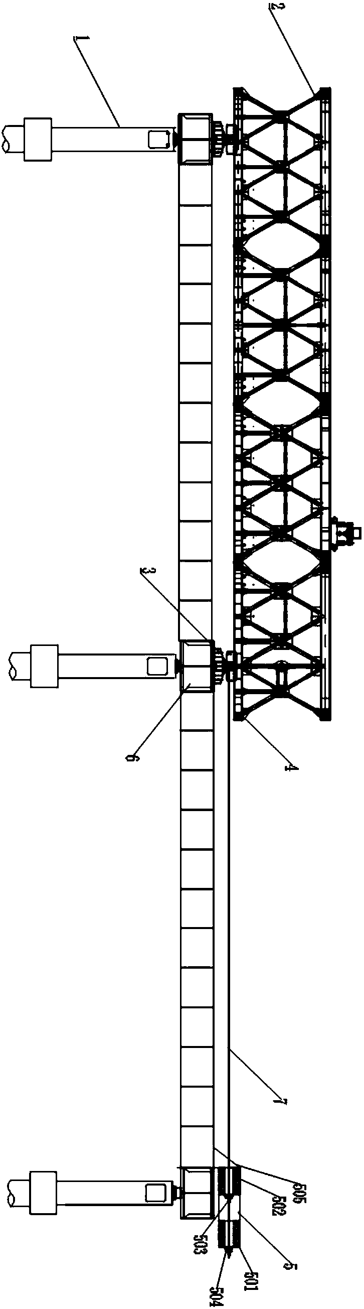
[0021] Such as figure 1 As shown, according to an embodiment of the present invention, a large-scale steel beam is based on a dragging device based on a finish-rolled rebar and a continuous hydraulic roof. A drag sliding structure 3 is provided at the drag point between the pier 1 and the steel beam 2. The sliding structure 3 is connected to the continuous dragging structure 5 through the finished rolled rebar 7, and the dragging sliding structure 3 is slidably ...


PUM


Abstract

The invention relates to a dragging device of large steel beams based on finely rolled deformed steel bars and continuous hydraulic jacks. Dragging slide structures are arranged at dragging points between bridge piers and steel beams; the dragging slide structures are connected with continuous dragging structures through the finely rolled deformed steel bars; the dragging slide structures are in slide connection with the steel beams through dragging counterforce rails; the dragging counterforce rails are arranged along the bridge direction; displacement, pressure and distance measurement sensing components are arranged between each dragging slide structure and each bridge pier; each dragging slide structure communicates with a hydraulic station; each hydraulic station communicates with a field control unit; and each field control unit communicates with a main control unit and corresponding displacement, pressure and distance measurement sensing components. The invention also disclosesa construction method of the device. The dragging device and the construction method have the beneficial effects that erection of the steel beams across channels, railways and expressways in complex environments can be realized, dragging devices arranged on a plurality of bridge piers can be controlled simultaneously, and the dragging displacement can be ensured to be equal to the actual displacement of the steel beams.

Description

Technical field [0001] The invention relates to the technical field of bridge construction, and in particular to a large-scale steel beam traction device and a construction method based on fine-rolled screw steel and continuous hydraulic roof. Background technique [0002] With the large-scale infrastructure construction in China, the surrounding environment of the projects that need to be constructed is becoming more and more complex, especially the construction of bridge steel beams across waterways, expressways, and existing railway lines. In order not to affect the operation of the original facilities and ensure safety, no Cantilever assembly technology is allowed. Segmental hoisting requires large-scale machinery and equipment for transportation and hoisting. However, the existing continuous jacks are combined with steel stranded wire pulling (Announcement Nos. CN101831874A and CN102359071A). Continuous jacks pull steel beams or large structural parts through steel stranded w...

Claims


Application Information

Patent Timeline
IPC IPC(8): E01D21/00F15B21/00
CPCF15B21/00E01D21/00
Inventor 田兵杨晖吴楠徐建辉代和松刘本良秦俭
Owner 江西乔田重工有限公司
Why Eureka
Try Eureka