Independent non-rigid pier-based multipoint synchronous jacking device of multi-union multi-span steel beam, and construction method

A jacking device, non-rigid technology, applied in bridges, bridge construction, erection/assembly of bridges, etc., can solve problems such as impermissible and synchronous jacking, improve construction quality and speed, and solve damage risks Effect

Pending Publication Date: 2018-03-20
江西乔田重工有限公司
View PDF14 Cites 3 Cited by
  • Summary
  • Abstract
  • Description
  • Claims
  • Application Information

AI Technical Summary

Problems solved by technology

[0002] With the large-scale construction of China's infrastructure, the surrounding environment of the projects that need to be constructed is becoming increasingly complex, especially the construction of bridge steel beams that cross waterways, expressways, and existing railway lines. In order not to affect the operation of the original facilities and ensure safety, we do not The cantilever assembly process is allowed, and the segmental hoisting requires large-scale mechanical equipment for transportation and hoisting, while the existing continuous jacks are dragged with steel hinges (notification numbers CN101831874A and CN102359071A), each push point needs to be provided with a slideway, and due to The horizontal reaction force is relatively large, so it is necessary to reinforce the pier or directly fix the continuous jack at the front end of the slideway. In addition, due to the elastic modulus characteristics of the steel hinge line and the large number of steel hinge lines, each continuous jack collected and controlled in the system The displacement is transmitted through the unequal elastic elongation factors of the steel hinge line, and the effect of synchronous jacking cannot be achieved in actual construction.

Method used


Image

  • Independent non-rigid pier-based multipoint synchronous jacking device of multi-union multi-span steel beam, and construction method
  • Independent non-rigid pier-based multipoint synchronous jacking device of multi-union multi-span steel beam, and construction method
  • Independent non-rigid pier-based multipoint synchronous jacking device of multi-union multi-span steel beam, and construction method

Examples


Embodiment Construction

[0020] The following will clearly and completely describe the technical solutions in the embodiments of the present invention with reference to the accompanying drawings in the embodiments of the present invention. Obviously, the described embodiments are only some, not all, embodiments of the present invention. All other embodiments obtained by persons of ordinary skill in the art based on the embodiments of the present invention belong to the protection scope of the present invention.

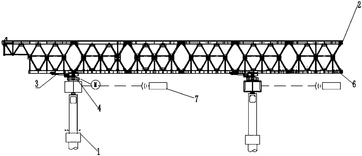
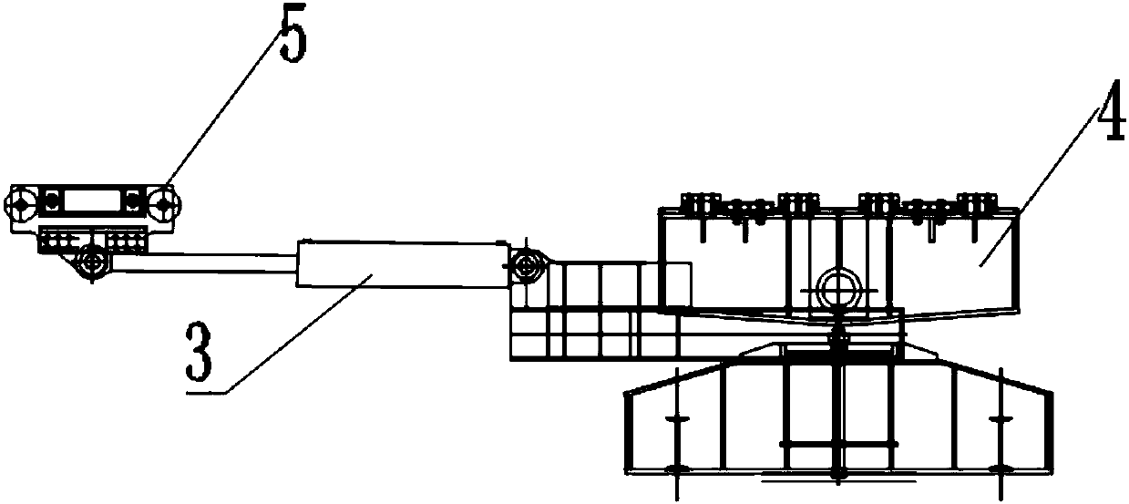
[0021] Such as Figure 1-3 As shown, according to the embodiment of the present invention 1. a multi-connected multi-span steel girder multi-point synchronous pushing device based on independent non-rigid piers, each pier 1 is provided with a hydraulic jack pushing unit 3, the The hydraulic jack pushing unit 3 is provided with a continuous pushing sliding structure 4, the hydraulic jack pushing unit 3 and the continuous pushing sliding mechanism 4 are connected to the steel beam 2 through the...


PUM


Abstract

The invention discloses an independent non-rigid pier-based multipoint synchronous jacking device of a multi-union multi-span steel beam. A hydraulic jacking unit is arranged on each pier, a continuous jacking sliding structure is arranged at the hydraulic jacking unit, the hydraulic jacking unit and the continuous jacking sliding structure are connected with the steel beam through a jacking counter force track, the jacking counter force track is distributed along with a bridge direction, a pin insertion and extraction system is arranged between the hydraulic jacking unit and the jacking counter force track, and a pier displacement ranging system is arranged between the continuous jacking sliding structure and the pier; and the invention further discloses a construction method of the device. The independent non-rigid pier-based multipoint synchronous jacking device of multi-union multi-span steel beam has the beneficial effects of being capable of controlling all independent piers to be synchronously jacked within the allowable displacement deviation range, so as to guarantee that the pier is not destroyed by jacking force, and the construction quality and speed of the steel beam can be improved.

Description

technical field [0001] The invention relates to the technical field of bridge construction, in particular to a multi-point synchronous jacking device and construction method for multi-connected multi-span steel girders based on independent non-rigid piers. Background technique [0002] With the large-scale construction of my country's infrastructure, the surrounding environment of the projects that need to be constructed is becoming increasingly complex, especially the construction of bridge steel beams that cross waterways, expressways, and existing railway lines. In order not to affect the operation of the original facilities and ensure safety, we do not The cantilever assembly process is allowed, and the segmental hoisting requires large-scale mechanical equipment for transportation and hoisting, while the existing continuous jacks are dragged with steel hinges (notification numbers CN101831874A and CN102359071A), each push point needs to be provided with a slideway, and du...

Claims


Application Information

Patent Timeline
IPC IPC(8): E01D21/06
CPCE01D21/06Y02P90/02
Inventor 田兵杨晖吴楠徐建辉代和松刘本良秦俭
Owner 江西乔田重工有限公司
Why Eureka
Try Eureka