Eureka AIR delivers breakthrough ideas for toughest innovation challenges, trusted by R&D personnel around the world.

Hardware protection circuit for photovoltaic inverter

A photovoltaic inverter and hardware protection technology, applied in safety/protection circuits, emergency protection circuit devices, photovoltaic power generation, etc., can solve the problem of large differences in the action time of protection points, large influence of hardware circuit temperature, and slow protection action time, etc. problem, to achieve good economic use value, fast fault response, and slow action time to solve the effect

Pending Publication Date: 2021-08-27
JIANGSU RCT POWER ENERGY TECH CO LTD
View PDF0 Cites 0 Cited by
  • Summary
  • Abstract
  • Description
  • Claims
  • Application Information

AI Technical Summary

Problems solved by technology

[0004] 1) The protection action time is slow, the actual protection operating point is slightly higher than the design value, and there is a certain risk of damage to the hardware circuit;
[0005] 2) Due to the presence of clamping diodes, the hardware circuit is greatly affected by temperature. At high and low temperatures, the action time of the protection point varies greatly
[0006] Therefore, if the hardware has a single point of failure (power switch tube failure), if the hardware protection is triggered and the fault cannot be completely disconnected, it will cause further hardware damage risks

Method used


Image

  • Hardware protection circuit for photovoltaic inverter
  • Hardware protection circuit for photovoltaic inverter
  • Hardware protection circuit for photovoltaic inverter

Examples


Embodiment Construction

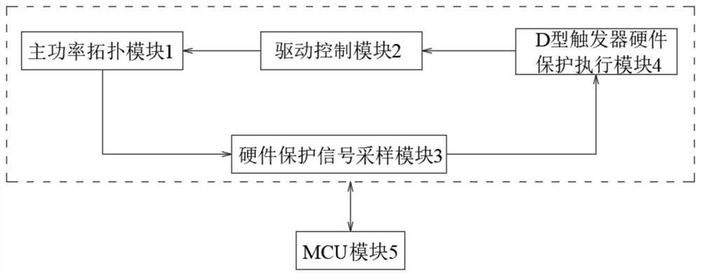
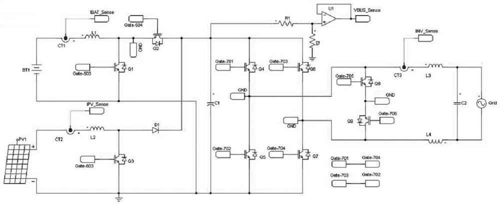
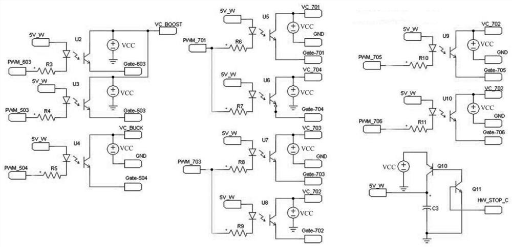
[0027] like Figure 1 to Figure 7 As shown, a hardware protection circuit for a photovoltaic inverter of the present invention includes:

[0028] The main power topology module 1 is connected with the hardware protection signal sampling module 3, and is used for fault signal detection and sends the signal to the hardware protection signal sampling module 3;

[0029] The drive control module 2 is connected to the main power topology module 1, and is used to provide a driving signal for the main power topology module 1;

[0030] The hardware protection signal sampling module 3 is connected with the D-type flip-flop hardware protection execution module 4, and is used to detect the fault signal received from the main power topology module 1, and send the generated trigger hardware fault signal to the D-type flip-flop hardware Protect execution module 4;

[0031] The D-type flip-flop hardware protection execution module 4 is connected to the drive control module 2, and is used to...


PUM


Abstract

The invention provides a hardware protection circuit for a photovoltaic inverter. The hardware protection circuit has the advantages that fault protection response time can be considered, and hardware comprehensive protection can still be effectively carried out when a hardware fault exists; The circuit comprises: a main power topology module used for detecting a fault signal and sending the signal to a hardware protection signal sampling module; a driving control module which is used for providing a driving signal for the main power topology module; a hardware protection signal sampling module which is used for detecting a fault signal received from the main power topology module and sending a generated trigger hardware fault signal to the D-type trigger hardware protection execution module; a D-type trigger hardware protection execution module which is used for blocking all driving signals after receiving the trigger hardware fault signal; and an MCU module which is connected with the main power topology module, the driving control module, the hardware protection signal sampling module and the D-type trigger hardware protection execution module, and is used for receiving signals of each functional module and feeding back the signals in time.

Description

technical field [0001] The invention relates to the technical field of photovoltaic inverters and energy storage, in particular to a hardware protection circuit for photovoltaic inverters. Background technique [0002] The hardware protection circuit of traditional photovoltaic inverters, such as OCP overcurrent protection, bus OVP overvoltage protection and other measures, are connected to the cathode of the diode at the protection design point, and the output end of the switch tube drive circuit is connected to the anode of the diode; when the hardware protection is not triggered, The protection design point is high level, the diode is cut off, and the power switch circuit is working normally. When an OCP or OVP fault is triggered, the corresponding protection design point level is converted from a normal high level to a low level, so the corresponding The output of the switching tube driving circuit is clamped to a low level, thereby disconnecting the power circuit to ach...

Claims


Application Information

Patent Timeline
Patent Type & Authority Applications(China)
IPC IPC(8): H02H7/122H02H3/08H02M7/48H02J7/00H02J7/35
CPCH02H3/08H02H7/122H02J7/35H02M7/48H02J7/00304Y02E10/56
Inventor 郭颖付洪金铭杨吴振国戴明华
Owner JIANGSU RCT POWER ENERGY TECH CO LTD
Why Eureka
Eureka Blog
Learn More