
Extruder adopting dynamic sealing structure

A dynamic sealing structure and extruder technology, applied in the direction of engine sealing, engine components, mechanical equipment, etc., can solve problems such as wear, elastic sealing ring 51 aging, and gap increase

Pending Publication Date: 2018-03-30
SIIICO TECH CO LTD
View PDF0 Cites 0 Cited by
  • Summary
  • Abstract
  • Description
  • Claims
  • Application Information

AI Technical Summary

Problems solved by technology

However, with the prolongation of the use time of the extruder, the sealing plane 501 of the rotating sealing ring 5 will be worn, and the elastic sealing ring 51 will also be aging, resulting in the rotor shaft end 20 and the rotating The gap between the sealing rings 5, and the gap between the rotary sealing ring 5 and the barrel 1 gradually increases

Method used


Image

  • Extruder adopting dynamic sealing structure
  • Extruder adopting dynamic sealing structure
  • Extruder adopting dynamic sealing structure

Examples


Embodiment Construction

[0021] The structure of the sealing ring applying the technical solution of the present invention and the extruder using the sealing ring will be further described below in conjunction with the accompanying drawings.

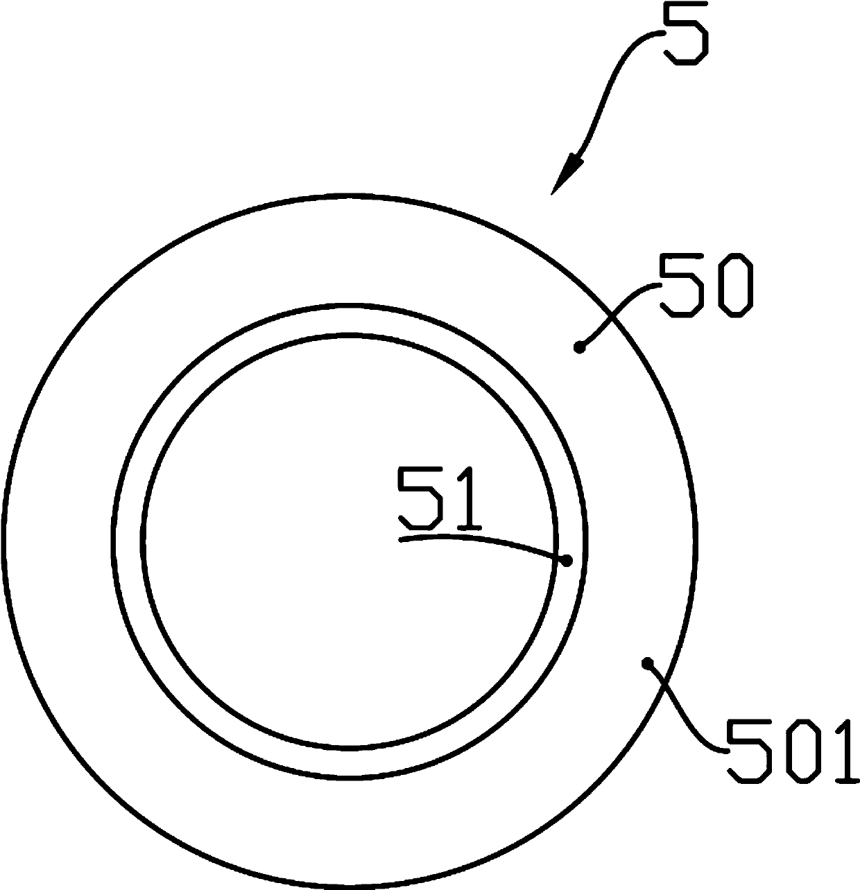
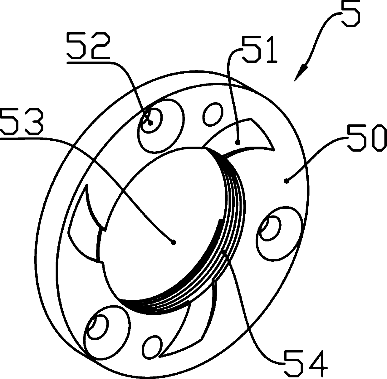
[0022] Such as image 3 , Figure 4 with Figure 5 Shown is a schematic structural view of the sealing ring 5, the sealing ring 5 has an axial central ring hole 53, the sealing ring 5 has a radially arranged sealing side wall surface 50, and three strips are arranged on the sealing side wall surface 50 The shallow aggregate pits 51 in the shape of a fan, of course, in other embodiments, a pair or more of the shallow aggregate pits 51 are also feasible. The axis of the collection shallow pits 51 is arc-shaped and all the collection shallow pits 51 are arranged on the outer periphery of the central ring hole 53 in the same deflection direction, and the inner of the collection shallow pits 51 The end communicates with the central annular hole 53, and the depth o...


PUM


Abstract

The invention relates to an extruder adopting a dynamic sealing structure. The extruder comprises a material barrel, a rotor and a sealing ring. The sealing ring is provided with an axial center ringhole and a sealing side wall face arranged in the radial direction. The sealing side wall face is provided with at least one pair of shallow collecting pits with the arc axes. All the shallow collecting pits are arranged on the periphery of the center ring hole in the same deflection direction, and the inner ends of the shallow collecting pits communicate with the center ring hole. The depths of the shallow collecting pits are gradually increased from exterior to interior. The sealing ring sleeves the shaft stretching end of the rotor in a penetrating manner through the center ring hole, and the sealing side wall face of the sealing ring is closely attached to the material barrel. The extruder further comprises a power device capable of driving the sealing ring to rotate. Under driving ofthe power device, and the rotating direction of the sealing ring is opposite to the deflection direction of the shallow collecting pits so that materials collected in the shallow collecting pits can be pushed in the direction of the center ring hole. At least one of the hole side wall of the center ring hole and the shaft side wall of the corresponding hole side wall of the shaft stretching end isprovided with a sealing spiral groove, and accordingly a dynamic seal can be formed.

Description

technical field [0001] The invention relates to an extruder adopting a dynamic sealing structure. Background technique [0002] With the rapid development of modern industry, the service environment of mechanical seals is undergoing profound changes, and the requirements for their working conditions are more stringent, and they are developing in the direction of high speed, high pressure, low temperature, and high vacuum. Taking an extruder as an example, the extruder is a kind of plastic machinery. Such as figure 1 As shown, the extruder includes a barrel 1 for storing materials, a rotor 2 for stirring the materials is arranged in the barrel 1, and a driving device 3 for driving the rotor 2 to rotate, so The output end 30 of the driving device 3 is connected to the shaft extension end 20 of the rotor 2 , and the output end 30 is rotatably arranged on the barrel 1 through the bearing 4 . The material to be processed is generally raw material powder, which is put into the ...

Claims


Application Information

Patent Timeline
IPC IPC(8): F16J15/40B29C47/08
CPCF16J15/406B29C48/254
Inventor 张伟明
Owner SIIICO TECH CO LTD
Learn More