Charging device

A charging device and conveying device technology, applied in the direction of circuit devices, battery circuit devices, charging stations, etc., can solve the problems of only being able to wait, prolong the time for users to reach their destination, and waste users' precious time, so as to achieve smooth transportation and improve The effect of ease of use

Inactive Publication Date: 2018-03-30
罗昌兴
View PDF0 Cites 0 Cited by
  • Summary
  • Abstract
  • Description
  • Claims
  • Application Information

AI Technical Summary

Problems solved by technology

[0002] Most of the existing charging devices are used to charge the battery of the mobile device. When charging, the mobile device needs to be connected to the charging device to charge the battery on it, which means that the mobile device needs to be connected to the charging device for a long time. Until the battery is fully charged, therefore, this affects the use of mobile devices to a certain extent, such as electric vehicles. As we all know, one of the biggest problems existing in electric vehicles is the battery life problem. When it is a long distance, it needs to be charged at a certain distance, and when charging, the user can only wait, which prolongs the time for the user to reach the destination, and wastes the user's precious time to a certain extent

Method used


Image

  • Charging device
  • Charging device

Examples


Embodiment Construction

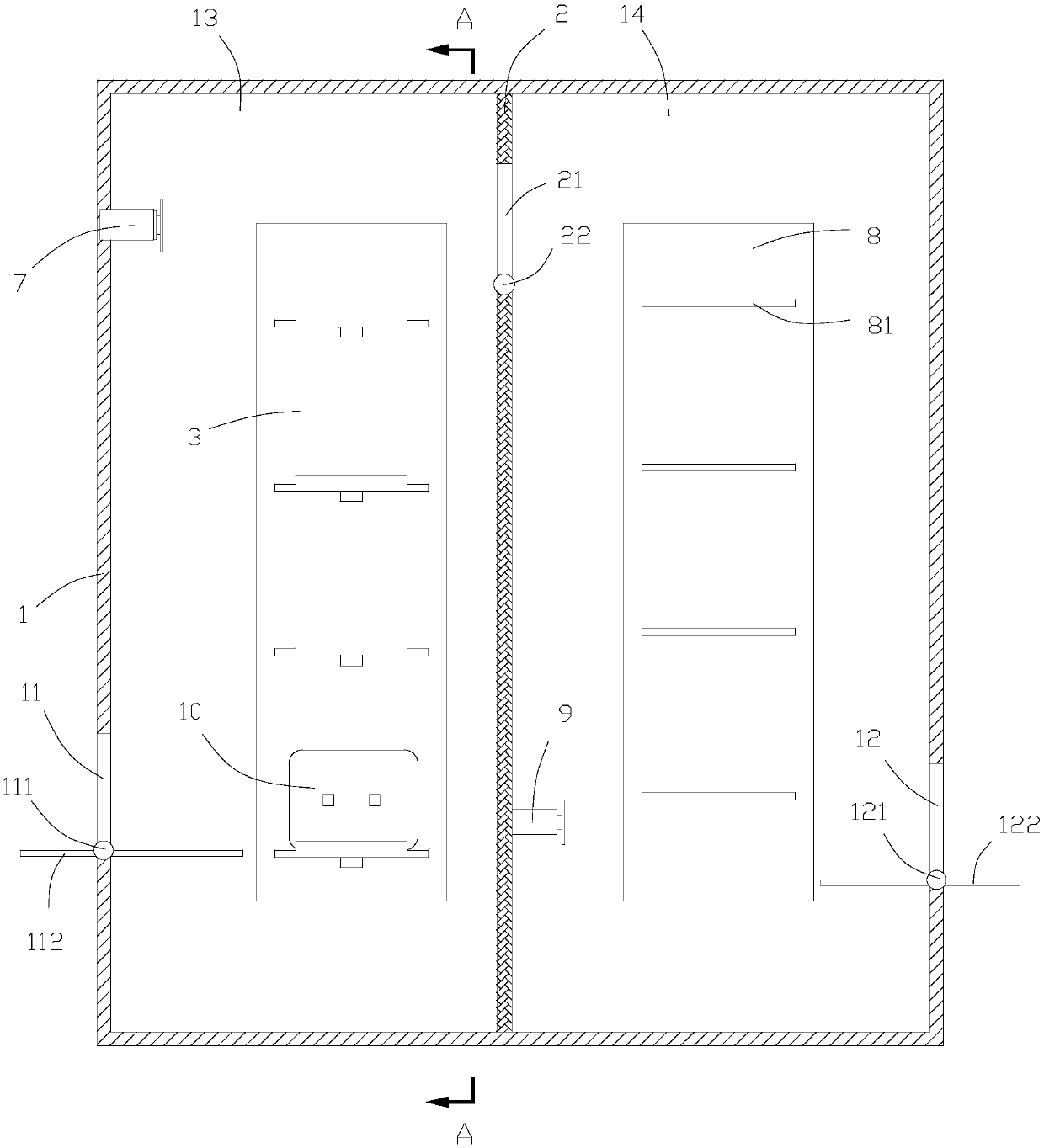
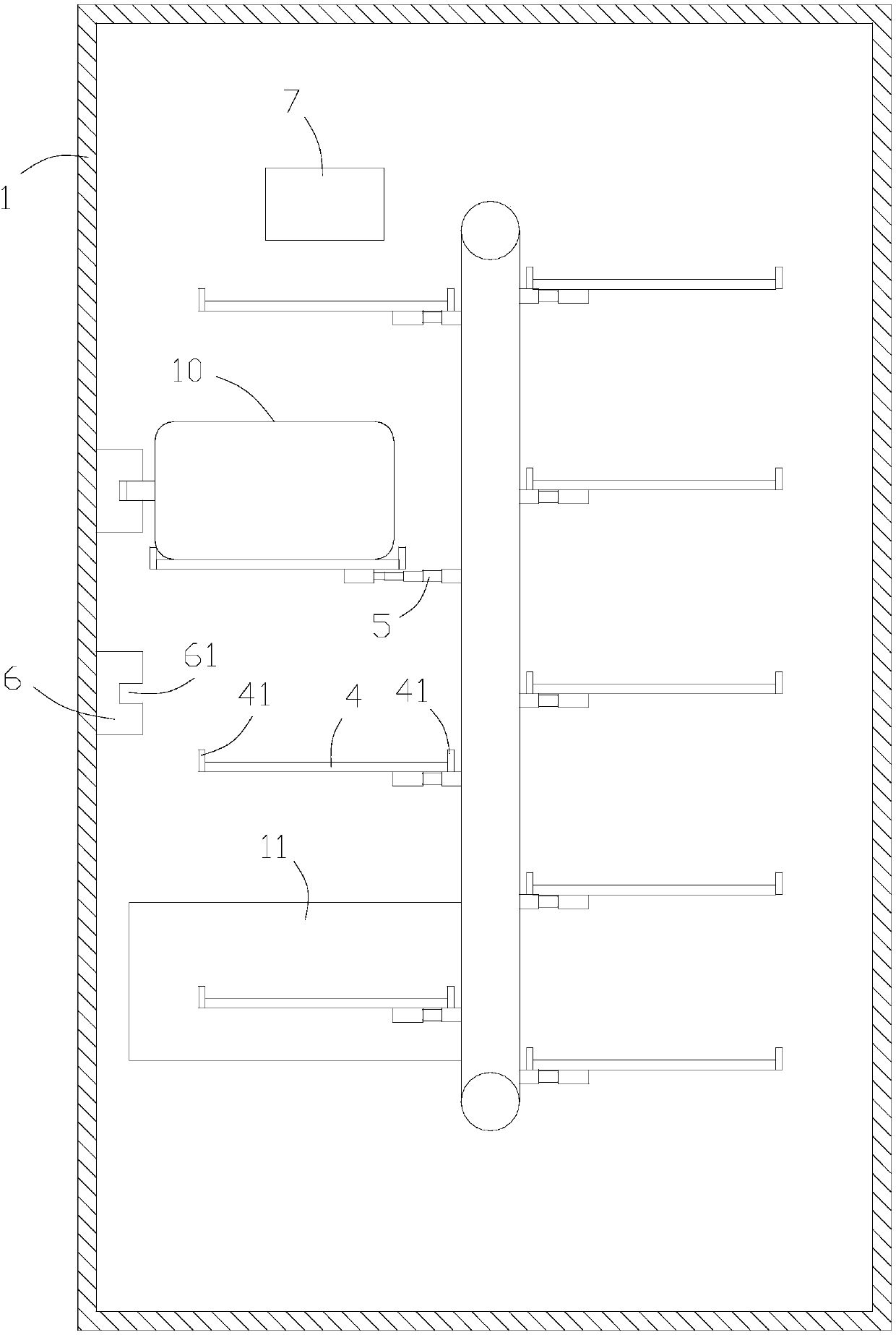
[0025] See figure 1 with figure 2 In a preferred embodiment of the present invention, a charging device is used to match a battery 10 whose poles are convex and whose positive and negative poles are on the same side. The charging device includes a casing 1. The housing 1 is provided with an inlet 11 and an outlet 12 for communicating the inside and the outside. The housing 1 is provided with a first conveying device 3, the first conveying device 3 is arranged vertically, and its conveying surface is perpendicular to The entrance 11 is on the surface, and a plurality of first supporting plates 4 are arranged on the conveying surface at intervals. The first supporting plates 4 are used to hold the battery 10 coming in from the inlet 11, and the battery 10 is The supporting surfaces are perpendicular to the surface where the entrance 11 is located and the conveying surface of the first conveying device 3; the first supporting plate 4 is installed on the first conveying device 3 t...


PUM


Abstract

The invention discloses a charging device which is used for matching the battery of which the electrode posts are outwardly convex and the positive and negative electrode posts are arranged at the same side. The charging device comprises a shell which is provided with an inlet and an outlet. The shell is internally provided with a first conveying device. The conveying surface of the first conveying device is provided with multiple first carrying plates in a spaced way. The first carrying plates are installed on the first conveying device through first telescopic members. The first telescopic members can drive the first carrying plates to stretch and contract. Charging members are arranged in the stretching direction of the first telescopic members. The charging members are arranged on theshell, and one side, which faces the first telescopic members, of each charging member is provided with a charging part. The charging part is connected with the positive and negative electrode posts of the battery on each first carrying plate. One side, which faces the charging member, of each first carrying plate is provided with a limiting baffle plate protruding out of the carrying surface. Theshell is also internally provided with a first push member. The first push member is arranged on the opposite side of the outlet and exactly faces the outlet. The first push member has a telescopic function. Replacing and charging of the battery can be realized.

Description

Technical field [0001] The invention relates to the field of battery charging devices, in particular to a charging device. Background technique [0002] Existing charging devices are mostly used to charge the batteries of mobile devices. When charging, the mobile device needs to be connected to the charging device and then the battery on it is charged. This means that the mobile device needs to be connected to the charging device for a long time. Until the battery is full, therefore, this affects the use of mobile devices to a certain extent, such as electric vehicles. As we all know, one of the larger problems existing in existing electric vehicles is battery life. When electric vehicles are running on the road, they When it is a long distance, it needs to be charged at a distance, but when charging, the user can only wait, which prolongs the time for the user to reach the destination and wastes the user's precious time to a certain extent. Therefore, related researchers have c...

Claims


Application Information

Patent Timeline
Patent Type & Authority Applications(China)
IPC IPC(8): H02J7/00B60L11/18
CPCB60L53/30B60L53/80H02J7/0027H02J7/0042Y02T10/70Y02T10/7072Y02T90/12
Inventor 罗昌兴
Owner 罗昌兴
Why Eureka
Try Eureka