
A method and system for improving the performance of shield cutting tool cemented carbide

A technology of cemented carbide and shield cutting tools, applied in the field of alloys, can solve problems such as insufficient density, reduced hardness and wear resistance, and tool fracture, and achieve the effect of enhancing mechanical properties and thermal conductivity and heat dissipation performance

Inactive Publication Date: 2020-10-30
STATE KEY LAB OF SHIELD & TUNNELING TECH +1
View PDF4 Cites 0 Cited by
  • Summary
  • Abstract
  • Description
  • Claims
  • Application Information

AI Technical Summary

Problems solved by technology

[0007] The modification of cemented carbide in the prior art only improves the mechanical properties of cemented carbide through various technological means, while ignoring the specific conditions used. For shield cutting tools, the improvement of mechanical properties of strength and toughness is a key factor. On the one hand, the improvement of heat conduction and heat dissipation is a point that needs to be emphasized. When the temperature rises, the mechanical properties such as mechanical strength and hardness will drop sharply. However, many existing technologies are purely based on mechanical properties.
[0008] At the same time, the existing shield cutting tools are generally completed by hot pressing and sintering, and there will be a large number of defects. In the process of use, the defects will become the source of cracks. In the process of repeated use, the cyclic stress can easily cause it to crack, resulting in The fracture of the same casting is not enough, so that the hardness and wear resistance are reduced

Method used


Image

  • A method and system for improving the performance of shield cutting tool cemented carbide
  • A method and system for improving the performance of shield cutting tool cemented carbide
  • A method and system for improving the performance of shield cutting tool cemented carbide

Examples


Embodiment example 1

[0053] Implementation case 1 The preparation method of the graphene-doped cemented carbide is:

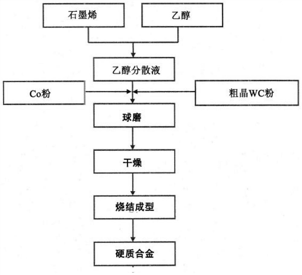
[0054] Weigh a certain mass of WC and Co powder. The content of Co powder accounts for 6wt% of the alloy raw materials. The graphene of 1% by weight relative to Co is ultrasonically dispersed in ethanol for 30 minutes, and then the ethanol suspension of the graphene is used as The ball milling medium is mixed with WC and Co powder by ball milling, ball milled in a planetary ball mill at 120 rpm for 4 hours, and then vacuum-dried for SPS sintering. The sintering temperature is 1200 degrees Celsius, the axial pressure is 80 MPa, and the heat preservation time is 10 minutes. The furnace is cooled to obtain a cemented carbide doped with graphene. Its performance is shown in Table 1.

Embodiment example 2

[0055] Implementation case 2 The difference between this implementation case and implementation case 1 is that the amount of graphene added is 1.5 wt% of the amount of Co, and its performance is shown in Table 1.

Embodiment example 3

[0056] Implementation case 3 The difference between this implementation case and implementation case 1 is that the amount of graphene added is 2wt% of the amount of Co, and its properties are shown in Table 1.


PUM

PropertyMeasurementUnit
hardnessaaaaaaaaaa

Abstract

The invention belongs to the technical field of alloys, and discloses a method and a system for improving the hard alloy performance of a shield cutter. The method comprises the following steps: aftergraphene is uniformly dispersed in an organic solvent in advance to form dispersion liquid, the graphene is mixed with coarse grain WC powder and CO powder, and then hard alloy of the shield cutter is prepared through the ball milling, drying and sintering process in sequence. The graphene is subjected to ultrasonic vibration dispersion in the organic solvent and is subjected to long-time ball milling with hard alloy raw material powder, so that a good mixing effect can be achieved, and thus the structure is uniform in the subsequent sintering process, and sintering defects are reduced. The excellent heat conduction performance and comprehensive mechanical properties of the grapheme are utilized, so that the heat conduction property of the hard alloy is enhanced and the mechanical property of the hard alloy is enhanced.

Description

Technical field [0001] The invention belongs to the technical field of alloys, and in particular relates to a method and a system for improving the performance of hard alloys of shield tools. Background technique [0002] Cemented carbide is a composite material composed of high hardness, high melting point metal carbides (WC, TiC) as the matrix and cobalt (Co), nickel (Ni) or molybdenum (Mo) as the binder phase. Cemented carbide has a unique combination of properties, that is, good wear resistance, high hardness, high compressive strength, high elastic modulus, strong impact resistance, high corrosion resistance, dimensional stability, etc. Shield cutter heads are generally made of coarse-grained WC-Co cemented carbide. [0003] Research on shield tool failure mechanism and tool temperature shows that the main failure modes of tools during shield construction are fracture and wear. Both failure phenomena are closely related to the temperature of the tool, such as the impact of WC...

Claims


Application Information

Patent Timeline
Patent Type & Authority Patents(China)
IPC IPC(8): B22F9/24C22C1/05C22C29/08
CPCB22F9/24C22C1/051C22C29/067C22C29/08
Inventor 孙振川肖文凯罗序军宋睿琨王晗
Owner STATE KEY LAB OF SHIELD & TUNNELING TECH
Learn More