Micro-angle-adjustable anti-rotation tool

A technology of anti-rotation and tools, which is applied in the direction of manufacturing tools, hand-held tools, threaded fasteners, etc. It can solve the problems that the position of the edge of the nut or bolt cannot be calibrated, it cannot be flexibly used in multiple places, and it is laborious to remove or install the bolt. , to avoid the inconvenience of support, to choose flexibly, and to ensure the effect of tightening torque

Pending Publication Date: 2018-04-03
潍坊威广机器人科技有限公司
View PDF5 Cites 2 Cited by
  • Summary
  • Abstract
  • Description
  • Claims
  • Application Information

AI Technical Summary

Problems solved by technology

[0002] When screwing bolts and nuts, the tightening effect will be affected by the rotation of the nut or bolt at the other end
The methods currently used mostly require the use of manpower, and the two ends need to be used together, and two tools are used to position them respectively. However, in many cases, the two ends cannot be matched, which makes it very laborious to disassemble or install the bolts. There are anti-rotation structures for bolt pairs, but most of these devices adopt fixed structures, which cannot be flexibly applied in multiple places, resulting in the need to make different anti-rotation devices when facing different working conditions. Secondly, sometimes due to the influence of obstacles, resulting in Traditional tools cannot be applied
[0003] With the further application of this tool, the edge position of the nut or bolt is sometimes unable to be calibrated. Since the reference of the current auxiliary tools is fixed and cannot be adjusted, the hole of the limit nut has been finalized, and the bolt or bolt to be disassembled or The nut cannot be twisted. Once the hole of the limit nut is matched with the nut, the angle of the other fixed reference is fixed, which makes it impossible to achieve the final fixation.

Method used


Image

  • Micro-angle-adjustable anti-rotation tool

Examples


Embodiment Construction

[0023] In order to facilitate the understanding of those skilled in the art, the present invention will be further described below in conjunction with the accompanying drawings.

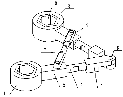
[0024] Such as figure 1 As shown, a fine-tuning angle anti-rotation tool includes two positioning blocks 1, and two positioning blocks 1 are provided with limit holes 9, and the limit holes 9 are used to limit the rotation of nuts or bolts to be disassembled. Connecting handles 2 are arranged on the top, and the other ends of the two connecting handles 2 are all provided with lockable telescopic rods 3, and the other ends of the two telescopic rods 3 are all provided with connectors 4. Both ends of the rod are threadedly connected to the connecting handle 2 and the connecting head 4 respectively, and the other ends of the two connecting heads 4 are hinged through the rotating shaft 5, and a mounting hole is also provided on the two connecting handles 2;

[0025] Also includes a positioning handle, t...


PUM


Abstract

The invention discloses a micro-angle-adjustable anti-rotation tool, and belongs to the field of equipment tools. The micro-angle-adjustable anti-rotation tool comprises two locating blocks and a locating handle, wherein the two locating blocks are provided with limiting holes; the limiting holes are used for limiting nuts or bolts to be disassembled from rotating; the two locating blocks are provided with a connection handle respectively; the other ends of the two connection handles are provided with a lockable telescopic rod respectively; the other ends of the two telescopic rods are provided with a connector respectively; the other ends of the two connectors are hinged through a rotating shaft; the two connection handles are also provided with one mounting hole respectively; the locating handle consists of two segments of locating joints and one screw rod; the screw rod is arranged between the two segments of locating joints; the screw rod is in threaded connection with the two locating joints; the other ends of the two locating joints are respectively provided with a connection hole matched with the mounting holes in the two connection handles.

Description

technical field [0001] The invention relates to the field of equipment tools, in particular to a fine-adjustment angle anti-rotation tool. Background technique [0002] When screwing bolts and nuts, the fastening effect will be affected by the rotation of the nut or bolt at the other end. The methods currently used mostly require the use of manpower, and the two ends need to be used together, and two tools are used to position them respectively. However, in many cases, the two ends cannot be matched, which makes it very laborious to disassemble or install the bolts. There are anti-rotation structures for bolt pairs, but most of these devices adopt fixed structures and cannot be flexibly used in multiple places, resulting in the need to make different anti-rotation devices when facing different working conditions. Secondly, sometimes due to the influence of obstacles, resulting in Traditional tools cannot be applied. [0003] With the further application of this tool, the e...

Claims


Application Information

Patent Timeline
Patent Type & Authority Applications(China)
IPC IPC(8): B25B27/00B25B27/14F16B39/02
CPCF16B39/02B25B27/00B25B27/14
Inventor 刘敏
Owner 潍坊威广机器人科技有限公司
Why Eureka
Try Eureka