
Rubber surface air-blowing device for drying and compounding machine

A technology of blowing device and drying machine, applied in printing device, lamination auxiliary operation, printing and other directions, can solve the problems of increasing the dosage of preparations such as viscose, the font becoming blurred, and trouble, so as to avoid the occurrence of paste code, Ensure normal and reliable operation, avoid the effect of dissolution

Active Publication Date: 2018-04-03
HUANGSHAN NOVEL
View PDF4 Cites 0 Cited by
  • Summary
  • Abstract
  • Description
  • Claims
  • Application Information

AI Technical Summary

Problems solved by technology

The existing problems in dry laminating production are as follows: firstly, at present, a large number of dry laminating machines use cold sealing technology, and cold sealing is to apply cold sealing glue on the inner layer of the film, and only need to add Pressure, use the viscosity of the cold sealant itself to achieve the purpose of bonding between the inner film
After the coding is completed, the inkjet characters are often unclear. This is due to the fact that the inkjet glue itself is easy to dissolve. Before entering the next process after the glue is sprayed, the complete inkjet font has actually begun to dissolve. blurred font
Finally, many film products are food-grade films, and the quality of the products is strictly controlled; in order to ensure the dryness of the film products, manufacturers have to increase the dosage of viscose and other preparations in order to obtain high-quality products. Difficult to have both and bear's paw, which brings many troubles to actual production

Method used


Image

  • Rubber surface air-blowing device for drying and compounding machine
  • Rubber surface air-blowing device for drying and compounding machine
  • Rubber surface air-blowing device for drying and compounding machine

Examples


Embodiment Construction

[0029] For ease of understanding, the specific structure and working method of the present invention are described as follows in conjunction with the accompanying drawings:

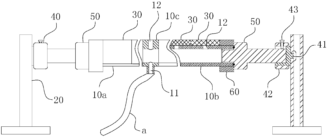
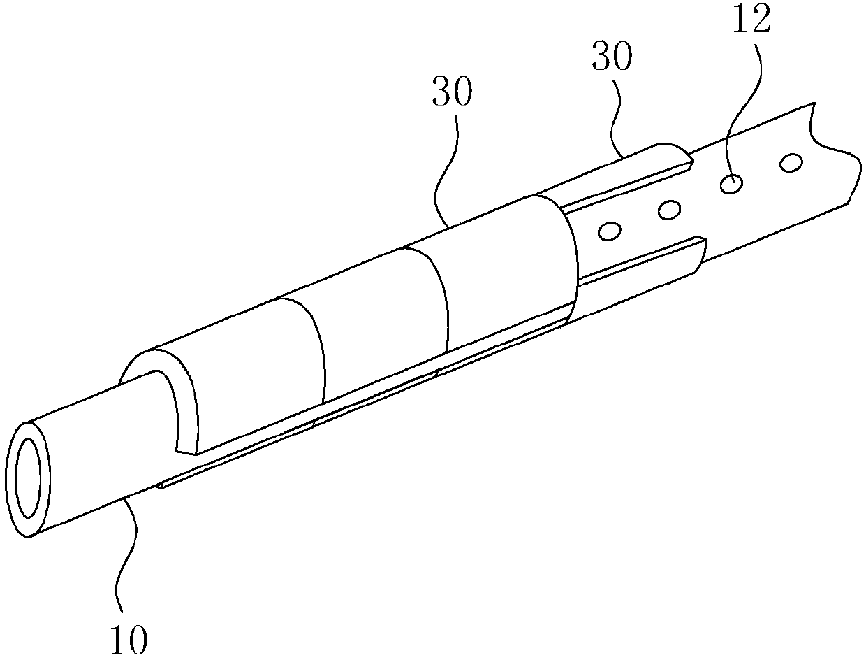
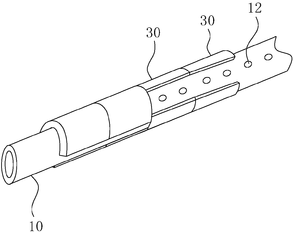
[0030] Concrete structure of the present invention refers to Figure 1-6 As shown, its main structure includes bracket 20, pipe end connector 40, connecting rod 50, left air pipe 10a, right air pipe 10b, connecting ring 10c, windshield ring 30 and backing ring 60, wherein:

[0031] Such as figure 1 As shown, the left air duct 10a and the right air duct 10b are arranged coaxially with each other and coaxially separated at the two ends of the connecting ring 10c, thereby forming the air duct 10 together with the connecting ring 10c. The connecting ring 10c itself has an air inlet 11, so as to communicate with external air supply equipment through the air inlet pipe a. A number of air outlets 12 are arranged axially in sequence on the connecting ring 10c and the left air duct 10a and the right air duct 10b...


PUM

PropertyMeasurementUnit
Axial lengthaaaaaaaaaa

Abstract

The invention belongs to the field of accessory equipment of a drying and compounding machine, and particularly relates to a rubber surface air-blowing device for the drying and compounding machine. The rubber surface air-blowing device comprises an air tube, and further comprises air blocking rings, wherein the two ends of the air tube are supported and fixed in the forms of simple supporting beams through brackets; air inlets and air outlets are formed in the air tube; the air outlets are sequentially formed in the tube length direction of the air tube; air outlet directions of the air outlets point to the film surface direction of a film; each air blocking ring has an air feeding state and a closed state; when each air blocking ring is in the air feeding state, opening of the air blocking ring in the form of a C-shaped arc-shaped sheet is positioned at air outlet paths of the air outlets; when each air blocking ring is in the closed state, the ring body of the air blocking ring shields air outlet paths of the air outlets; and the air blocking rings are sequentially arranged in the axial direction of the air tube. The rubber surface air-blowing device can ensure that a coiled cold sealing adhesive is always in a drying state, so that the rubber surface is prevented from a reverse pasting phenomenon; and meanwhile, fixed-point drying ability is strong, so that the fixed-pointdrying purpose is realized relative to code spraying position of the film.

Description

technical field [0001] The invention belongs to the field of auxiliary equipment for drying and compounding machines, and in particular relates to a rubber surface blowing device for drying and compounding machines. Background technique [0002] The dry laminating machine is a mechanical device that coats the solvent-diluted adhesive on the substrate after it dries, and then laminates it with other films by pressure rollers. The existing problems in dry laminating production are as follows: firstly, at present, a large number of dry laminating machines use cold sealing technology, and cold sealing is to apply cold sealing glue on the inner layer of the film, and only need to add Pressing, using the viscosity of the cold sealant itself can achieve the purpose of bonding between the inner film. In the cold sealing process, in addition to the choice of cohesive force of the cold sealant and the control of solvent residues, it is also necessary to control the dryness of the col...

Claims


Application Information

Patent Timeline
IPC IPC(8): B32B38/16B41J11/00
CPCB32B38/164B41J11/002Y02P70/10
Inventor 张春生王卫民凌家学王健
Owner HUANGSHAN NOVEL
Learn More