Hydraulic manipulator

A manipulator and hydraulic technology, applied in manipulators, chucks, manufacturing tools, etc., can solve the problems of bad electric-driven manipulators, high protection requirements, and high cost of construction, and achieve the effect of improving labor productivity, low protection level, and low cost.

Inactive Publication Date: 2018-04-06
周士忠
View PDF5 Cites 3 Cited by
  • Summary
  • Abstract
  • Description
  • Claims
  • Application Information

AI Technical Summary

Problems solved by technology

[0003] However, most of the industrial manipulators in the current industrial assembly line are driven by electricity, which has certain limitations, high cost, and high protection requirements. The price of large electric-driven manipulators can be said to be very high. Some roughing applications are unacceptable in the industry, and the environment in the roughing industry is also a bit bad for electric drive manipulators

Method used


Image

  • Hydraulic manipulator

Examples


Embodiment Construction

[0011] The preferred embodiments of the present invention will be described in detail below in conjunction with the accompanying drawings, so that the advantages and features of the invention can be more easily understood by those skilled in the art, so as to define the protection scope of the present invention more clearly.

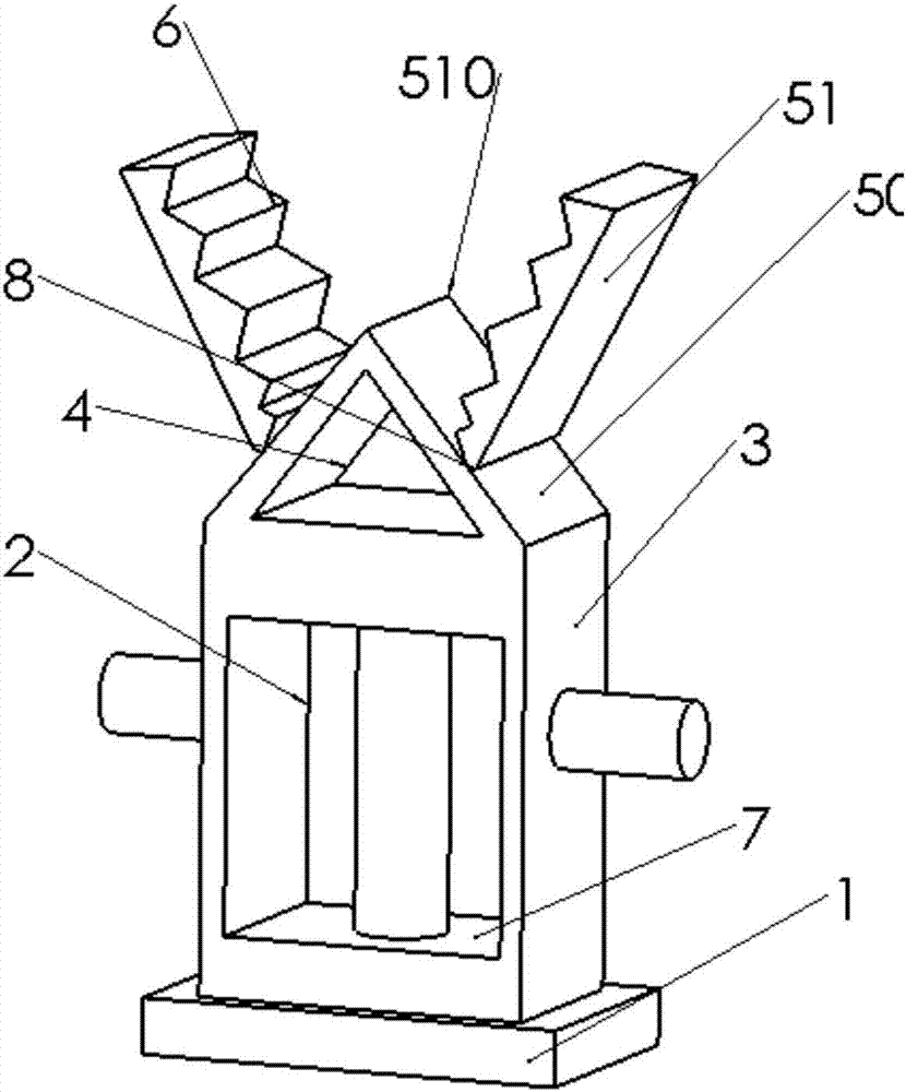
[0012] A hydraulic manipulator, the rotary hydraulic manipulator of the large-scale hydraulic manipulator includes a frame 1, a rotary cylinder 2, a manipulator cylinder outer cavity 3, a piston rod 4, and a manipulator device 5; the left end of the shell of the rotary cylinder 2 is screwed The frame 1 is fixed, the rotating shaft 7 of the rotary oil cylinder 2 is integrated with the outer chamber 3 of the manipulator oil cylinder, and the right end of the outer chamber 3 of the manipulator oil cylinder is fixedly connected with the manipulator device 5. 51, and the two are rollingly connected; hydraulic oil enters the rotary cylinder 2 to push the piston...


PUM


Abstract

The invention provides a hydraulic manipulator. The front end of the hydraulic manipulator is rotatable. The hydraulic manipulator comprises a rack, a rotating oil cylinder, a manipulator oil cylinderexternal cavity, a manipulator oil cylinder piston rod and a manipulator part device. The rack is fixed to the left end of a shell of the rotating oil cylinder through screws. A rotating shaft of therotating oil cylinder and the manipulator oil cylinder external cavity are integrated. The manipulator part device is fixed to the right end of the manipulator oil cylinder external cavity and composed of a manipulator fixing seat and a manipulator part. The fixing seat is movably connected with the middle of the manipulator part. The left end of the manipulator part is connected with the manipulator oil cylinder piston rod. The manipulator part is provided with at least one antiskid device. The hydraulic manipulator adopts pure hydraulic driving, grasping and releasing of a finger gripper are achieved, movement is flexible and diverse, the structure is compact, the weight is low, the efficiency is high, the hydraulic manipulator can be used in a harsh industrial environment, the protection level requirement is low, the working force of the hydraulic manipulator is much higher than that of an electric driven manipulator with the same level, and the cost of the hydraulic manipulator ismuch lower.

Description

【Technical field】 [0001] The invention relates to a machining tool, in particular to a rotatable hydraulic manipulator of a hydraulic large-scale manipulator. 【Background technique】 [0002] In recent years, with the widespread application of electronic technology, especially electronic computers, a large number of automated machinery has replaced workers to complete a large number of mechanized manual operations, and can also replace manual work in relatively harsh environments. At the same time, its high-speed work Efficiency is also unmatched by workers; similarly, automated machinery does not need to rest, and it can work 24 hours a day. In today's era of such high labor costs, it is necessary to develop automation to replace labor; the development and production of robots has become An emerging technology rapidly developed in the field of high-tech technology, it further promotes the development of manipulators, enabling manipulators to better realize the organic combin...

Claims


Application Information

Patent Timeline
IPC IPC(8): B25J15/00
CPCB25J15/00
Inventor 周士忠
Owner 周士忠
Why Eureka
Try Eureka