Supercharge Your Innovation With Domain-Expert AI Agents!

Anti-looseness supporting device for cable bridge

A technology for cable trays and supporting devices, which is applied in the direction of electrical components, etc., can solve problems such as unsatisfactory installation of cable trays, cable damage of cable trays, troublesome cable maintenance, etc., and achieve the effects of convenient laying, saving installation time, and convenient repair and maintenance

Inactive Publication Date: 2018-04-06
JIANGSU YIDINGGU ELECTROMECHANICAL TECH CO LTD
View PDF0 Cites 0 Cited by
  • Summary
  • Abstract
  • Description
  • Claims
  • Application Information

AI Technical Summary

Problems solved by technology

[0003] The cable tray is generally installed on the roof through the support device. After long-term use, the internal cables of the cable tray may be damaged and need to be repaired. Generally, the cable tray is fixed and disassembled by bolts, which may cause trouble for cable maintenance and waste maintenance. Time; when the cable tray is laid, the height of the supporting surface for installation may be different, and the general support device may not be able to meet the installation requirements of the cable tray.

Method used


Image

  • Anti-looseness supporting device for cable bridge
  • Anti-looseness supporting device for cable bridge
  • Anti-looseness supporting device for cable bridge

Examples


Embodiment Construction

[0018] The following will clearly and completely describe the technical solutions in the embodiments of the present invention with reference to the accompanying drawings in the embodiments of the present invention. Obviously, the described embodiments are only some, not all, embodiments of the present invention. Based on the embodiments of the present invention, all other embodiments obtained by persons of ordinary skill in the art without making creative efforts belong to the protection scope of the present invention.

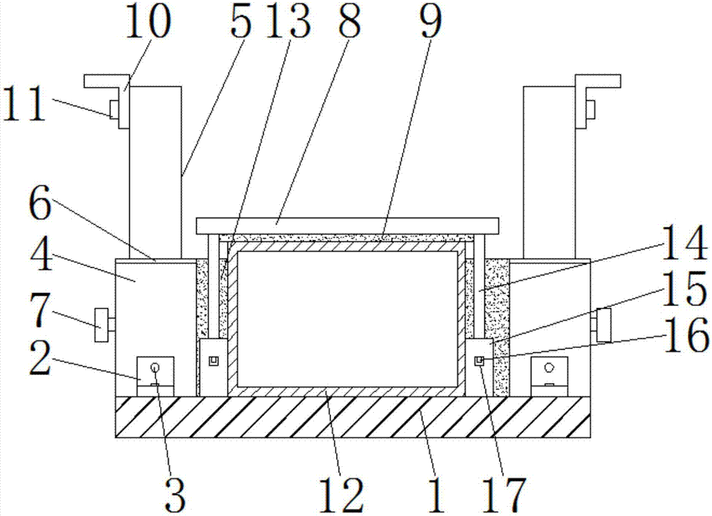
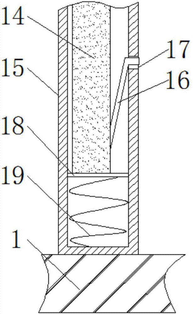
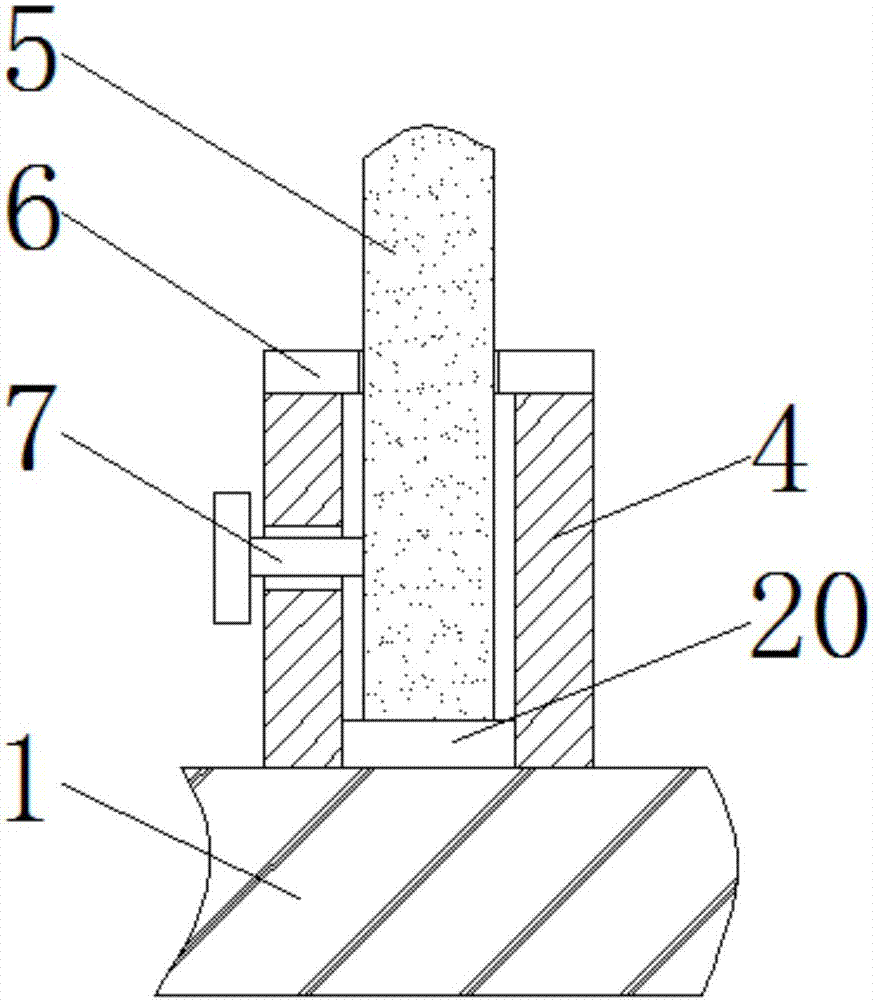
[0019] see Figure 1-3 As shown, a supporting device for a cable tray includes a bottom plate 1, the bottom plate 1 is fixedly connected with a sleeve 4 through a first connecting block 2, and the sleeve 4 and the bottom plate 1 are connected to the first bolt 3 through a first bolt 3. The connecting block 2 is fixedly connected, the inside of the sleeve 4 is sleeved with an inner rod 5, and the end of the inner rod 5 extends to the outside of the sleeve 4, an...


PUM


Abstract

The invention discloses a supporting device for a cable bridge, which includes a bottom plate, a first connecting block, a first bolt, a sleeve, an inner rod, a limit piece, a second bolt, a pressure block, a rubber strip, a second connecting block, The third bolt, cable tray, rubber block, connecting rod, sleeve, block, slot, connecting piece, spring and piston head. The invention has reasonable structure and novel design. The connecting rod compresses the spring through the connecting piece, and the spring provides elastic force for the connecting rod, so that the clamping block is tightly pressed in the clamping groove, so that the pressing block is fixed, and the pressing block is pressed tightly on the top of the cable bridge. The cable tray is fixed, which facilitates the installation of the cable tray and saves the installation time of the cable tray. By pushing the block, the spring makes the connecting rod pop out through the elastic force, which facilitates the disassembly of the pressing block and the connecting rod, thus facilitating the maintenance of the cable tray. and maintenance.

Description

technical field [0001] The invention relates to a supporting device for a cable bridge, in particular to a supporting device for a cable bridge, and belongs to the technical field of application of the supporting device for a cable bridge. Background technique [0002] Cable trays are divided into trough type, tray type, ladder type, grid type and other structures, and are composed of brackets, brackets and installation accessories; the bridges in buildings can be erected independently, or attached to various buildings and pipe gallery brackets superior. [0003] The cable tray is generally installed on the roof through the supporting device. After long-term use, the internal cables of the cable tray may be damaged and need to be repaired. Generally, the cable tray is fixed and disassembled by bolts, which may cause trouble for cable maintenance and waste maintenance. Time; when the cable tray is laid, the height of the supporting surface for installation may be different, ...

Claims


Application Information

Patent Timeline
IPC IPC(8): H02G3/04
CPCH02G3/0437
Inventor 杨鑫易佳楠陶家康蔡庆创李翔
Owner JIANGSU YIDINGGU ELECTROMECHANICAL TECH CO LTD
Features
  • R&D
  • Intellectual Property
  • Life Sciences
  • Materials
  • Tech Scout
  • Unparalleled Data Quality
  • Higher Quality Content
  • 60% Fewer Hallucinations
Learn More