Method, equipment and system for bearing service
A technology for carrying services and services, which is applied in the field of network communication and can solve the problems of inability to meet the application scenarios of PTN services, too large granularity, and small granularity of single time slot bandwidth.
- Summary
- Abstract
- Description
- Claims
- Application Information
AI Technical Summary
Problems solved by technology
Method used
Image

Examples
Embodiment 1
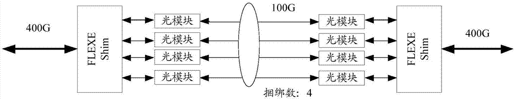
[0082] see Figure 6 , which shows a service bearer method provided by an embodiment of the present invention. In this embodiment, figure 1 The shown FLEXE network structure is taken as an example for illustration. The FLEXE network structure includes a service sending end and a receiving end. The method includes:
[0083] S601: The sending end determines the position of the bearer time slot used to bear the service to be transmitted;
[0084] S602: The sending end determines the position of the bearer data block group used to bear the service to be transmitted;
[0085] S603: The sending end transmits the service to be transmitted according to the position of the bearer time slot and the position of the bearer data block group;
[0086] S604: The receiving end determines the location of the received data block group used to carry the service to be received;
[0087] S605: The receiving end determines the position of the receiving time slot for carrying the service to be re...
Embodiment 2
[0108] Based on the same technical concept as the foregoing embodiments, this embodiment describes the technical solutions of the foregoing embodiments through specific examples.
[0109] For example, there are three services, namely service A, service B and service C; among them, the bandwidth of service A data is 2.5G, the bandwidth of service B data is 7.5G, and the bandwidth of service C is 1.25G.
[0110] Therefore, for the service data of service A, the configurations performed by the sender are time slot number {1}, data block group number {1, 3, 5 and other odd numbers}; that is, the sender carries the data of service A Send at the No. 1 time slot position in the block group whose data block group number is odd, and correspondingly, the receiving end will also receive the data block at the No. 1 time slot position in the block group whose data block group number is odd;
[0111] For the service data of service B, the sending end includes two groups of location configur...
Embodiment 3
[0119] Based on the same technical idea of the foregoing embodiments, see Figure 8 , which shows a service bearer method provided by an embodiment of the present invention, this method can be applied to figure 1 For the sending end in the shown FLEXE network structure, the method may include:
[0120] S801: The sending end determines the position of the bearer time slot used to bear the service to be transmitted;
[0121] S802: The sending end determines the position of the bearer data block group used to bear the service to be transmitted;
[0122] S803: The sending end transmits the service to be transmitted according to the position of the bearer time slot and the position of the bearer data block group.
[0123] Exemplarily, before step S801, the method further includes:
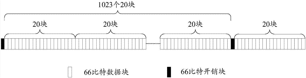
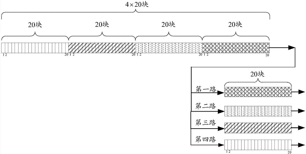
[0124] The sender numbers the time slots in the Calendar of the FLEXE protocol, and numbers the data block groups within the coverage of the overhead block.
[0125] Specifically, the sender can n...
PUM
 Abstract
Description
Claims
Application Information
 - R&D
- Intellectual Property
- Life Sciences
- Materials
- Tech Scout
- Unparalleled Data Quality
- Higher Quality Content
- 60% Fewer Hallucinations
Browse by: Latest US Patents, China's latest patents, Technical Efficacy Thesaurus, Application Domain, Technology Topic, Popular Technical Reports.
© 2025 PatSnap. All rights reserved.Legal|Privacy policy|Modern Slavery Act Transparency Statement|Sitemap|About US| Contact US: help@patsnap.com